- 您现在的位置:买卖IC网 > PDF目录1898 > ADM1024ARUZ-R7 (ON Semiconductor)IC MONITOR SYS TEMP/VOLT 24TSSOP PDF资料下载
参数资料
| 型号: | ADM1024ARUZ-R7 |
| 厂商: | ON Semiconductor |
| 文件页数: | 6/30页 |
| 文件大小: | 0K |
| 描述: | IC MONITOR SYS TEMP/VOLT 24TSSOP |
| 产品变化通告: | MFG CHG Notification ADI to ON Semi Product Discontinuation 30/Sept/2011 |
| 标准包装: | 1,000 |
| 应用: | PC,PDA |
| 接口: | 串行 |
| 电源电压: | 2.8 V ~ 5.5 V |
| 封装/外壳: | 24-TSSOP(0.173",4.40mm 宽) |
| 供应商设备封装: | 24-TSSOP |
| 包装: | 带卷 (TR) |
| 安装类型: | 表面贴装 |
第1页第2页第3页第4页第5页当前第6页第7页第8页第9页第10页第11页第12页第13页第14页第15页第16页第17页第18页第19页第20页第21页第22页第23页第24页第25页第26页第27页第28页第29页第30页
ADM1024
http://onsemi.com
14
Table 8. TEMPERATURE DATA FORMAT
Temperature
Digital Output
128C
1000 0000
125C
1000 0011
100C
1001 1100
75C
1011 0101
50C
1100 1110
25C
1110 0111
0C
0000 0000
+0.5C
0000 0000
+10C
0000 1010
+25C
0001 1001
+50C
0011 0010
+75C
0100 1011
+100C
0110 0100
+125C
0111 1101
+127C
0111 1111
Layout Considerations
Digital boards can be electrically noisy environments, and
care must be taken to protect the analog inputs from noise,
particularly when measuring the very small voltages from a
remote diode sensor. The following precautions should be
taken:
1. Place the ADM1024 as close as possible to the
remote sensing diode. Provided that the worst
noise sources such as clock generators,
data/address buses, and CRTs are avoided, this
distance can be 4 inches to 8 inches.
2. Route the D+ and D tracks close together, in
parallel, with grounded guard tracks on each side.
Provide a ground plane under the tracks if
possible.
3. Use wide tracks to minimize inductance and
reduce noise pickup. A 10 mil track minimum
width and spacing is recommended.
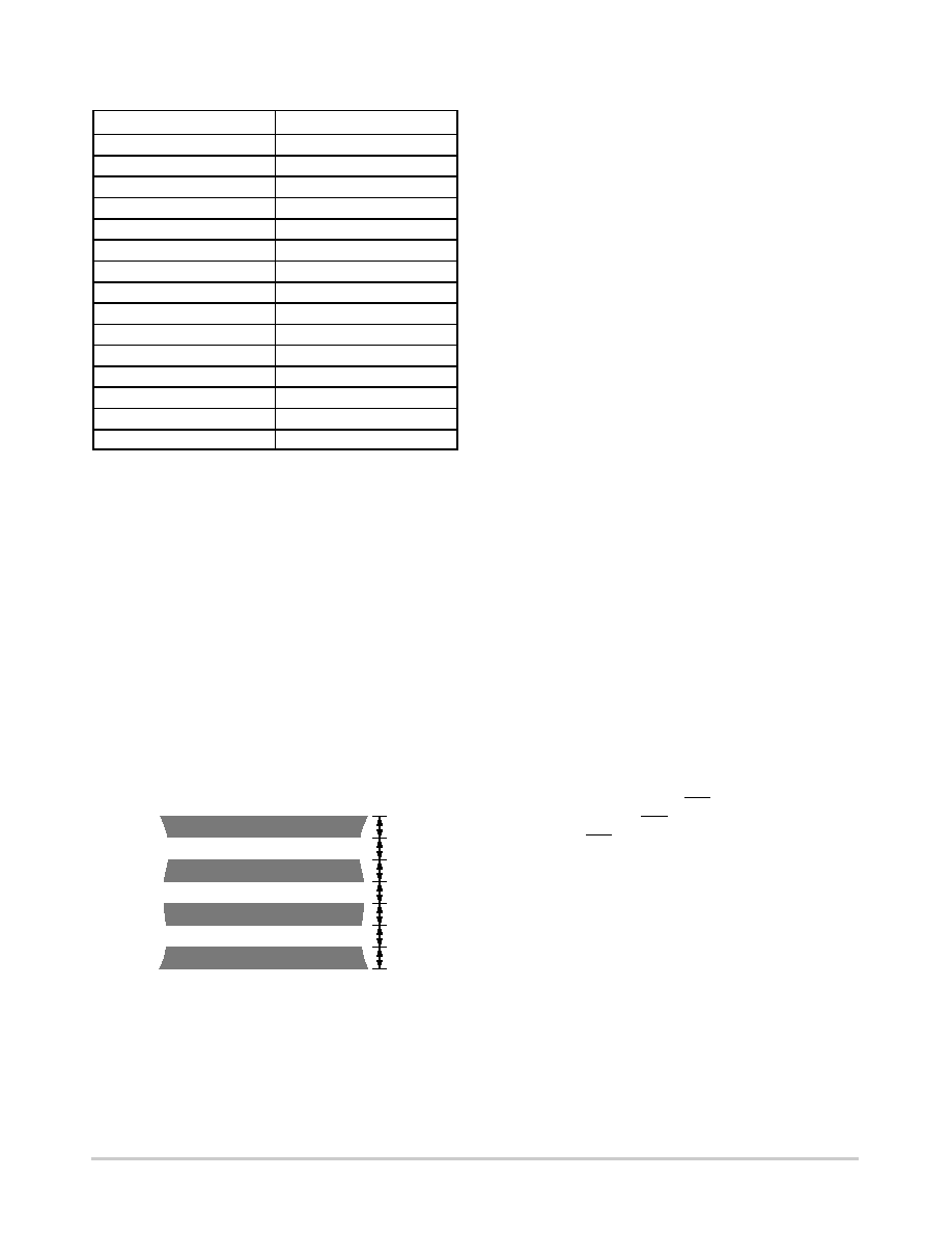
Figure 18. Arrangement of Signal Tracks
10MIL
GND
D+
GND
D–
10MIL
4. Try to minimize the number of copper/solder joints,
which can cause thermocouple effects. Where
copper/solder joints are used, make sure that they
are in both the D+ and D– path and at the same
temperature. Thermocouple effects should not be a
major problem as 1C corresponds to about 240
mV,
and thermocouple voltages are about 3
mV/C of
temperature difference. Unless there are two
thermocouples with a big temperature differential
between them, thermocouple voltages should be
much less than 200 mV.
5. Place 0.1
mF bypass and 2200 pF input filter
capacitors close to the ADM1024.
6. If the distance to the remote sensor is more than
8 inches, the use of twisted pair cable is
recommended. This will work up to about 6 feet to
12 feet.
7. For really long distances (up to 100 feet) use
shielded twisted pair such as Belden #8451
microphone cable. Connect the twisted pair to D+
and D– and the shield to GND close to the
ADM1024. Leave the remote end of the shield
unconnected to avoid ground loops.
Because the measurement technique uses switched
current sources, excessive cable and/or filter capacitance
can affect the measurement. When using long cables, the
filter capacitor may be reduced or removed.
Cable resistance can also introduce errors. A 1
W series
resistance introduces about 0.5C error.
Limit Values
Limit values for analog measurements are stored in the
appropriate limit registers. In the case of voltage
measurements, high and low limits can be stored so that an
interrupt request will be generated if the measured value
goes above or below acceptable values. In the case of
temperature, a Hot Temperature or High Limit can be
programmed, and a Hot Temperature Hysteresis or Low
Limit, which will usually be some degrees lower. This can
be useful as it allows the system to be shut down when the
hot limit is exceeded, and restarted automatically when it has
cooled down to a safe temperature.
Monitoring Cycle Time
The monitoring cycle begins when a 1 is written to the
Start Bit (Bit 0), and a 0 to the INT_Clear Bit (Bit 3) of the
Configuration Register. INT_Enable (Bit 1) should be set to
1 to enable the INT output. The ADC measures each analog
input in turn; as each measurement is completed, the result
is automatically stored in the appropriate value register. This
“round robin” monitoring cycle continues until it is disabled
by writing a 0 to Bit 0 of the Configuration Register.
As the ADC will normally be left to free-run in this
manner, the time taken to monitor all the analog inputs will
normally not be of interest, as the most recently measured
value of any input can be read out at any time.
For applications where the monitoring cycle time is
important, it can be calculated as follows:
(eq. 6)
m
t1 ) n t2
where:
m the number of inputs configured as analog inputs, plus the
internal VCC measurement and internal temperature sensor.
相关PDF资料 |
PDF描述 |
|---|---|
| ADM1025ARQZ-R7 | IC MONITOR SYS/VOLT 5CH 16QSOP |
| ADM1181AAN | IC TXRX RS-232 5V 15KV 16DIP |
| ADM1385ARS | IC TXRX RS-232 HI-SP 3.3V 20SSOP |
| ADM1485ARMZ-REEL7 | IC TXRX RS-485 5V HS 8MSOP |
| ADM1486AR | IC TX/RX RS-485 PRO-BUS 5V 8SOIC |
相关代理商/技术参数 |
参数描述 |
|---|---|
| ADM1024ARUZ-REEL | 功能描述:板上安装温度传感器 THERMAL & VOLT MONITOR IC RoHS:否 制造商:Omron Electronics 输出类型:Digital 配置: 准确性:+/- 1.5 C, +/- 3 C 温度阈值: 数字输出 - 总线接口:2-Wire, I2C, SMBus 电源电压-最大:5.5 V 电源电压-最小:4.5 V 最大工作温度:+ 50 C 最小工作温度:0 C 关闭: 安装风格: 封装 / 箱体: 设备功能:Temperature and Humidity Sensor |
| ADM1024ARUZ-REEL7 | 功能描述:IC MONITOR SYS TEMP/VOLT 24TSSOP RoHS:是 类别:集成电路 (IC) >> 接口 - 专用 系列:- 标准包装:3,000 系列:- 应用:PDA,便携式音频/视频,智能电话 接口:I²C,2 线串口 电源电压:1.65 V ~ 3.6 V 封装/外壳:24-WQFN 裸露焊盘 供应商设备封装:24-QFN 裸露焊盘(4x4) 包装:带卷 (TR) 安装类型:表面贴装 产品目录页面:1015 (CN2011-ZH PDF) 其它名称:296-25223-2 |
| ADM1024EVB | 功能描述:BOARD EVAL FOR ADM1024 RoHS:否 类别:编程器,开发系统 >> 过时/停产零件编号 系列:- 标准包装:1 系列:- 传感器类型:CMOS 成像,彩色(RGB) 传感范围:WVGA 接口:I²C 灵敏度:60 fps 电源电压:5.7 V ~ 6.3 V 嵌入式:否 已供物品:成像器板 已用 IC / 零件:KAC-00401 相关产品:4H2099-ND - SENSOR IMAGE WVGA COLOR 48-PQFP4H2094-ND - SENSOR IMAGE WVGA MONO 48-PQFP |
| ADM1025 | 制造商:AD 制造商全称:Analog Devices 功能描述:Low-Cost PC Hardware Monitor ASIC |
| ADM1025A | 制造商:AD 制造商全称:Analog Devices 功能描述:Low-Cost PC Hardware Monitor ASIC |
发布紧急采购,3分钟左右您将得到回复。