- 您现在的位置:买卖IC网 > PDF目录14911 > ADP2147ACBZ-110-R7 (Analog Devices Inc)IC REG BUCK SYNC 0.8A 6WLCSP PDF资料下载
参数资料
| 型号: | ADP2147ACBZ-110-R7 |
| 厂商: | Analog Devices Inc |
| 文件页数: | 13/16页 |
| 文件大小: | 0K |
| 描述: | IC REG BUCK SYNC 0.8A 6WLCSP |
| 产品变化通告: | 8mm Carrier Tape Changes 28/Feb/2012 |
| 标准包装: | 1 |
| 类型: | 降压(降压) |
| 输出类型: | 固定 |
| 输出数: | 1 |
| 输出电压: | 1.275V,0.981V |
| 输入电压: | 2.3 V ~ 5.5 V |
| PWM 型: | 电流模式 |
| 频率 - 开关: | 3MHz |
| 电流 - 输出: | 800mA |
| 同步整流器: | 是 |
| 工作温度: | -40°C ~ 85°C |
| 安装类型: | 表面贴装 |
| 封装/外壳: | 6-UFBGA,WLCSP |
| 包装: | 标准包装 |
| 供应商设备封装: | 6-WLCSP(1.03x1.50) |
| 其它名称: | ADP2147ACBZ-110-R7DKR |
�� ��
��
��ADP2147�
�APPLICATIONS� INFORMATION�
�EXTERNAL� COMPONENT� SELECTION�
�Trade-offs� between� performance� parameters� such� as� efficiency�
�and� transient� response� can� be� made� by� varying� the� choice� of�
�external� components� in� the� applications� circuit,� as� shown� in�
��Inductor�
�The� high� switching� frequency� of� the� ADP2147� allows� for� the�
�selection� of� small� chip� inductors.� For� best� performance,� use�
�inductor� values� between� 0.7� μH� and� 3� μH.� Recommended�
��The� peak-to-peak� inductor� current� ripple� is� calculated� using�
�the� following� equation:�
�Ceramic� capacitors� are� manufactured� with� a� variety� of� dielectrics,�
�each� with� different� behavior� over� temperature� and� applied� voltage.�
�Capacitors� must� have� a� dielectric� adequate� to� ensure� the�
�minimum� capacitance� over� the� necessary� temperature� range�
�and� dc� bias� conditions.� X5R� or� X7R� dielectrics� with� a� voltage�
�rating� of� 6.3� V� or� 10� V� are� recommended� for� best� performance.�
�Y5V� and� Z5U� dielectrics� are� not� recommended� for� use� with� any�
�dc-to-dc� regulator� because� of� their� poor� temperature� and� dc� bias�
�characteristics.�
�The� worst-case� capacitance,� accounting� for� capacitor� variation�
�over� temperature,� component� tolerance,� and� voltage,� is�
�calculated� using� the� following� equation:�
�C� EFF� =� C� OUT� � (1� ?� TEMPCO� )� � (1� ?� TOL� )�
�V� � (� V� IN� ?� V� OUT� )�
�I� RIPPLE�
�=� OUT�
�V� IN� � f� SW� � L�
�where:�
�C� EFF� is� the� effective� capacitance� at� the� operating� voltage.�
�where:�
�f� SW� is� the� switching� frequency.�
�L� is� the� inductor� value.�
�The� minimum� dc� current� rating� of� the� inductor� must� be� greater�
�than� the� inductor� peak� current.� The� inductor� peak� current� is�
�calculated� using� the� following� equation:�
�TEMPCO� is� the� worst-case� capacitor� temperature� coefficient.�
�TOL� is� the� worst-case� component� tolerance.�
�In� this� example,� the� worst-case� temperature� coefficient� (TEMPCO)�
�over� ?40°C� to� +85°C� is� assumed� to� be� 15%� for� an� X5R� dielectric.�
�The� tolerance� of� the� capacitor� (TOL)� is� assumed� to� be� 10%,� and�
��I� PEAK� =� I� LOAD� (� MAX� )� +�
�I� RIPPLE�
�2�
�Substituting� these� values� in� the� equation� yields�
�C� EFF� =� 4.0466� μF� ×� (1� ?� 0.15)� ×� (1� ?� 0.1)� =� 3.0956� μF�
�Inductor� conduction� losses� are� caused� by� the� flow� of� current�
�through� the� inductor,� which� has� an� associated� internal� DCR.�
�Larger� sized� inductors� have� smaller� DCR,� which� may� decrease�
�inductor� conduction� losses.� Inductor� core� losses� are� related� to�
�the� magnetic� permeability� of� the� core� material.� Because� the�
�ADP2147� is� a� high� switching� frequency� dc-to-dc� regulator,�
�shielded� ferrite� core� material� is� recommended� for� its� low� core�
��shows� the� suggested� inductors� that� can� be� used� for� different�
�output� current� requirements;� several� inductors� are� also� listed� to�
�minimize� PCB� space� for� small� current� applications.�
�Table� 6.� Suggested� 1.0� μH� Inductors�
�To� guarantee� the� performance� of� the� ADP2147,� it� is� imperative�
�that� the� effects� of� dc� bias,� temperature,� and� tolerances� on� the�
�behavior� of� the� capacitors� be� evaluated� for� each� application.�
�6�
�5�
�4�
�3�
�2�
�Vendor�
�Model�
�Dimensions�
�(mm)�
�I� SAT�
�(mA)�
�DCR�
�(mΩ)�
�1�
�Murata�
�LQM2MPN1R0NG0B�
�LQM18PN1R0�
�2.0� � 1.6� � 0.9�
�1.6� � 0.8� � 0.33�
�1400�
�700�
�85�
�52�
�0�
�0�
�1�
�2� 3� 4�
�5�
�6�
�Coilcraft?�
�Toko�
�TDK�
�Taiyo� Yuden�
�EPL2014-102ML�
�0603LS-102�
�MDT2520-CN�
�GLFR1608T1R0M-LR�
�CBMF1608T1R0M�
�2.0� � 2.0� � 1.4�
�1.8� � 1.27� � 1.1�
�2.5� � 2.0� � 1.2�
�1.6� � 0.8� � 0.8�
�1.6� � 0.8� � 0.8�
�900�
�400�
�1800�
�360�
�290�
�59�
�81�
�100�
�80�
�90�
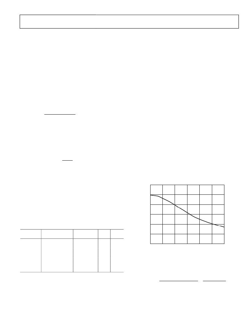
�DC� BIAS� VOLTAGE� (V)�
�Figure� 34.� Typical� Capacitor� Performance�
�The� peak-to-peak� output� voltage� ripple� for� the� selected� output�
�capacitor� and� inductor� values� is� calculated� using� the� following�
�equation:�
�Output� Capacitor�
�Increasing� the� value� of� the� output� capacitor� reduces� the� output�
�voltage� ripple� and� improves� load� transient� response.� When�
�V� RIPPLE� =�
�V� IN�
�(� 2� π� ×� f� SW� )� ×� 2� ×� L� ×� C� OUT�
�=�
�I� RIPPLE�
�8� � f� SW� � C� OUT�
�choosing� the� capacitor� value,� it� is� also� important� to� account� for�
�the� loss� of� capacitance� due� to� dc� output� voltage� bias.�
�Rev.� 0� |� Page� 13� of� 16�
�相关PDF资料 |
PDF描述 |
|---|---|
| ECA30DRMD-S664 | CONN EDGECARD 60POS .125 SQ WW |
| MAX6854UK27D4+T | IC MPU SUPERVISOR SOT23-5 |
| RBA40DTKN-S288 | CONN EDGECARD 80POS .125 EXTEND |
| MAX6854UK28D1+T | IC MPU SUPERVISOR SOT23-5 |
| RBA40DTKH-S288 | CONN EDGECARD 80POS .125 EXTEND |
相关代理商/技术参数 |
参数描述 |
|---|---|
| ADP2147ACBZ-130-R7 | 功能描述:IC REG BUCK SYNC 0.8A 6WLCSP RoHS:是 类别:集成电路 (IC) >> PMIC - 稳压器 - DC DC 开关稳压器 系列:- 标准包装:500 系列:- 类型:切换式电容器(充电泵),反相 输出类型:固定 输出数:1 输出电压:-3V 输入电压:2.3 V ~ 5.5 V PWM 型:Burst Mode? 频率 - 开关:900kHz 电流 - 输出:100mA 同步整流器:无 工作温度:-40°C ~ 85°C 安装类型:表面贴装 封装/外壳:SOT-23-6 细型,TSOT-23-6 包装:带卷 (TR) 供应商设备封装:TSOT-23-6 其它名称:LTC1983ES6-3#TRMTR |
| ADP2147ACBZ-150-R7 | 功能描述:IC REG BUCK SYNC 1.2V/1V 6WLCSP RoHS:是 类别:集成电路 (IC) >> PMIC - 稳压器 - DC DC 开关稳压器 系列:- 标准包装:500 系列:- 类型:切换式电容器(充电泵),反相 输出类型:固定 输出数:1 输出电压:-3V 输入电压:2.3 V ~ 5.5 V PWM 型:Burst Mode? 频率 - 开关:900kHz 电流 - 输出:100mA 同步整流器:无 工作温度:-40°C ~ 85°C 安装类型:表面贴装 封装/外壳:SOT-23-6 细型,TSOT-23-6 包装:带卷 (TR) 供应商设备封装:TSOT-23-6 其它名称:LTC1983ES6-3#TRMTR |
| ADP2147ACBZ-170-R7 | 功能描述:IC REG BUCK SYNC 0.8A 6WLCSP RoHS:是 类别:集成电路 (IC) >> PMIC - 稳压器 - DC DC 开关稳压器 系列:- 标准包装:500 系列:- 类型:切换式电容器(充电泵),反相 输出类型:固定 输出数:1 输出电压:-3V 输入电压:2.3 V ~ 5.5 V PWM 型:Burst Mode? 频率 - 开关:900kHz 电流 - 输出:100mA 同步整流器:无 工作温度:-40°C ~ 85°C 安装类型:表面贴装 封装/外壳:SOT-23-6 细型,TSOT-23-6 包装:带卷 (TR) 供应商设备封装:TSOT-23-6 其它名称:LTC1983ES6-3#TRMTR |
| ADP2147CB-110EVALZ | 功能描述:BOARD EVAL ADP2147ACBZ-110 RoHS:是 类别:编程器,开发系统 >> 评估板 - DC/DC 与 AC/DC(离线)SMPS 系列:* 产品培训模块:Obsolescence Mitigation Program 标准包装:1 系列:True Shutdown™ 主要目的:DC/DC,步升 输出及类型:1,非隔离 功率 - 输出:- 输出电压:- 电流 - 输出:1A 输入电压:2.5 V ~ 5.5 V 稳压器拓扑结构:升压 频率 - 开关:3MHz 板类型:完全填充 已供物品:板 已用 IC / 零件:MAX8969 |
| ADP2147CB-130EVALZ | 功能描述:BOARD EVAL ADP2147ACBZ-130 RoHS:是 类别:编程器,开发系统 >> 评估板 - DC/DC 与 AC/DC(离线)SMPS 系列:* 产品培训模块:Obsolescence Mitigation Program 标准包装:1 系列:True Shutdown™ 主要目的:DC/DC,步升 输出及类型:1,非隔离 功率 - 输出:- 输出电压:- 电流 - 输出:1A 输入电压:2.5 V ~ 5.5 V 稳压器拓扑结构:升压 频率 - 开关:3MHz 板类型:完全填充 已供物品:板 已用 IC / 零件:MAX8969 |
发布紧急采购,3分钟左右您将得到回复。