- 您现在的位置:买卖IC网 > PDF目录10372 > ADS7825UG4 (Texas Instruments)IC 16BIT 4-CHAN MUX ADC 28-SOIC PDF资料下载
参数资料
| 型号: | ADS7825UG4 |
| 厂商: | Texas Instruments |
| 文件页数: | 5/21页 |
| 文件大小: | 0K |
| 描述: | IC 16BIT 4-CHAN MUX ADC 28-SOIC |
| 产品培训模块: | Data Converter Basics |
| 标准包装: | 20 |
| 位数: | 16 |
| 采样率(每秒): | 40k |
| 数据接口: | 串行,并联 |
| 转换器数目: | 1 |
| 功率耗散(最大): | 50mW |
| 电压电源: | 单电源 |
| 工作温度: | -40°C ~ 85°C |
| 安装类型: | 表面贴装 |
| 封装/外壳: | 28-SOIC(0.295",7.50mm 宽) |
| 供应商设备封装: | 28-SOIC |
| 包装: | 管件 |
| 输入数目和类型: | 4 个单端,双极 |
13
ADS7825
DATACLK (pin 15). The data will be valid on both the
rising and falling edges of the internal data clock. The rising
edge of BUSY (pin 24) can be used to latch the data. After
the 16th clock pulse, DATACLK will remain LOW until the
next conversion is initiated, while SDATA will go to what-
ever logic level was input on TAG (pin 17) during the first
clock pulse. The SDATA output will tri-state when BUSY
returns HIGH. Refer to Table II and Figure 4 for timing
information.
EXTERNAL DATA CLOCK
To use an external clock, tie EXT/INT (pin 12) HIGH. The
external clock is not a conversion clock; it can only be used
as a data clock. To enable the output mode of the ADS7825,
CS (pin 23) must be LOW and R/C (pin 22) must be HIGH.
DATACLK must be HIGH for 20% to 70% of the total data
clock period; the clock rate can be between DC and 10MHz.
Serial data from conversion ‘n’ can be output on SDATA
(pin 16) after conversion ‘n’ is completed or during conver-
sion ‘n + 1’.
An obvious way to simplify control of the converter is to tie
CS LOW while using R/C to initiate conversions. While this
is perfectly acceptable, there is a possible problem when
using an external data clock. At an indeterminate point from
12
s after the start of conversion ‘n’ until BUSY rises, the
internal logic will shift the results of conversion ‘n’ into the
output register. If CS is LOW, R/C is HIGH and the external
clock is HIGH at this point, data will be lost. So, with CS
LOW, either R/C and/or DATACLK must be LOW during
this period to avoid losing valid data.
EXTERNAL DATA CLOCK (After a Conversion)
After conversion ‘n’ is completed and the output registers
have been updated, BUSY (pin 24) will go HIGH. With CS
LOW (pin 23) and R/C HIGH (pin 22), valid data from
conversion ‘n’ will be output on SDATA (pin 16) synchro-
nized to the external data clock input on DATACLK (pin
15). Between 15 and 35ns following the rising edge of the
first external data clock, the SYNC output pin will go HIGH
for one full data clock period (100ns minimum). The MSB
will be valid between 25 and 55ns after the rising edge of the
second data clock. The LSB will be valid on the 17th falling
edge and the 18th rising edge of the data clock. TAG (pin
17) will input a bit of data for every external clock pulse.
The first bit input on TAG will be valid on SDATA on the
18th falling edge and the 19th rising edge of DATACLK; the
second input bit will be valid on the 19th falling edge and the
20th rising edge, etc. With a continuous data clock, TAG
data will be output on DATA until the internal output
registers are updated with the results from the next conver-
sion. Refer to Table II and Figure 5 for timing information.
EXTERNAL DATA CLOCK (During a Conversion)
After conversion ‘n’ has been initiated, valid data from
conversion ’n-1’ can be read and will be valid up to 12
s
after the start of conversion ‘n’. Do not attempt to clock out
data from 12
s after the start of conversion ‘n’ until BUSY
(pin 24) rises; this will result in data loss.
NOTE: For the best possible performance when using an
external data clock, data should not be clocked out during a
conversion. The switching noise of the asynchronous data clock
can cause digital feedthrough degrading the converter’s perfor-
mance. Refer to Table II and Figure 6 for timing information.
TAG FEATURE
TAG (pin 17) inputs serial data synchronized to the external
or internal data clock.
When using an external data clock, the serial bit stream input
on TAG will follow the LSB output on SDATA (pin 16)
until the internal output register is updated with new conver-
sion results. See Table II and Figures 5 and 6.
The logic level input on TAG for the first rising edge of the
internal data clock will be valid on SDATA after all 16 bits
of valid data have been output.
MULTIPLEXER TIMING
The four channel input multiplexer may be addressed manu-
ally or placed in a continuous conversion mode where all
four channels are sequentially addressed.
CONTINUOUS CONVERSION MODE (CONTC = 5V)
To place the ADS7825 in the continuous conversion mode,
CONTC (pin 25) must be tied HIGH. In this mode, acquisi-
tion and conversions will take place continually, cycling
through all four channels as long as CS, R/C and PWRD are
LOW (See Table III). Whichever address was last loaded
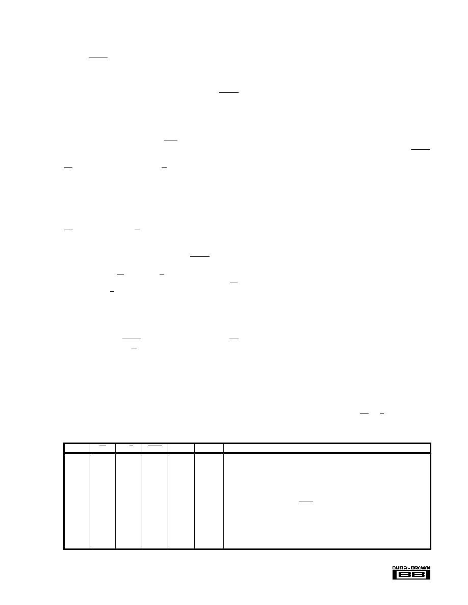
CONTC
CS
R/C
BUSY
PWRD
A0 and A1 OPERATION
0
X
Inputs
Initiating conversion n latches in the levels input on A0 and A1 to select the channel for
conversion 'n + 1'.
0
X
0
Inputs
Conversion in process. New convert commands ignored.
00
↓
1
0
Inputs
Initiates conversion on channel selected at start of previous conversion.
0
↓
0
1
0
Inputs
Initiates conversion on channel selected at start of previous conversion.
0
X
1
Inputs
All analog functions powered down. Conversions in process or initiated will yield
meaningless data.
1
X
Outputs
The end of conversion 'n' (when BUSY rises) increments the internal channel latches and
outputs the channel address for conversion 'n + 1' on A0 and A1.
1
X
0
Outputs
Conversion in process.
10
↓
1
0
Outputs
Restarts continuous conversion process on next input channel.
1
↓
0
1
0
Outputs
Restarts continuous conversion process on next input channel.
1
X
1
Outputs
All analog functions powered down. Conversions in process or initiated will yield
meaningless data. Resets selected input channel for next conversion to AIN0.
TABLE III. Conversion Control.
相关PDF资料 |
PDF描述 |
|---|---|
| D38999/20JD5AN | CONN HSG RCPT 5POS WALL MT PINS |
| D38999/20WB98SNLC | CONN HSG RCPT 6POS WALL MT SCKT |
| ADS7825UE4 | IC 16BIT 4-CHAN MUX ADC 28-SOIC |
| MS27473E8F98PLC | CONN HSG PLUG 3POS STRGHT PINS |
| MS27484T16B35SLC | CONN HSG PLUG 55POS STRGHT SCKT |
相关代理商/技术参数 |
参数描述 |
|---|---|
| ADS7826 | 制造商:TI 制造商全称:Texas Instruments 功能描述:10/8/12-BIT HIGH SPEED 2.7 V microPOWER SAMPLING ANALOG-TO-DIGITAL CONVERTER |
| ADS7826EVM | 功能描述:数据转换 IC 开发工具 ADS7826 Eval Mod RoHS:否 制造商:Texas Instruments 产品:Demonstration Kits 类型:ADC 工具用于评估:ADS130E08 接口类型:SPI 工作电源电压:- 6 V to + 6 V |
| ADS7826I | 制造商:TI 制造商全称:Texas Instruments 功能描述:10/8/12-BIT HIGH SPEED 2.7 V microPOWER SAMPLING ANALOG-TO-DIGITAL CONVERTER |
| ADS7826IDRBR | 功能描述:模数转换器 - ADC 5.25V-2.7V 10 bit 200KSPS Synch Serial RoHS:否 制造商:Texas Instruments 通道数量:2 结构:Sigma-Delta 转换速率:125 SPs to 8 KSPs 分辨率:24 bit 输入类型:Differential 信噪比:107 dB 接口类型:SPI 工作电源电压:1.7 V to 3.6 V, 2.7 V to 5.25 V 最大工作温度:+ 85 C 安装风格:SMD/SMT 封装 / 箱体:VQFN-32 |
| ADS7826IDRBRG4 | 功能描述:模数转换器 - ADC 5.25V-2.7V 10 bit 200KSPS Synch Serial RoHS:否 制造商:Texas Instruments 通道数量:2 结构:Sigma-Delta 转换速率:125 SPs to 8 KSPs 分辨率:24 bit 输入类型:Differential 信噪比:107 dB 接口类型:SPI 工作电源电压:1.7 V to 3.6 V, 2.7 V to 5.25 V 最大工作温度:+ 85 C 安装风格:SMD/SMT 封装 / 箱体:VQFN-32 |
发布紧急采购,3分钟左右您将得到回复。