- 您现在的位置:买卖IC网 > PDF目录19393 > ADSP-2185NBSTZ-320 (Analog Devices Inc)IC DSP CONTROLLER 16BIT 100LQFP PDF资料下载
参数资料
| 型号: | ADSP-2185NBSTZ-320 |
| 厂商: | Analog Devices Inc |
| 文件页数: | 9/48页 |
| 文件大小: | 0K |
| 描述: | IC DSP CONTROLLER 16BIT 100LQFP |
| 标准包装: | 1 |
| 系列: | ADSP-21xx |
| 类型: | 定点 |
| 接口: | 主机接口,串行端口 |
| 时钟速率: | 80MHz |
| 非易失内存: | 外部 |
| 芯片上RAM: | 80kB |
| 电压 - 输入/输出: | 1.8V,2.5V,3.3V |
| 电压 - 核心: | 1.90V |
| 工作温度: | -40°C ~ 85°C |
| 安装类型: | 表面贴装 |
| 封装/外壳: | 100-LQFP |
| 供应商设备封装: | 100-LQFP(14x14) |
| 包装: | 托盘 |
第1页第2页第3页第4页第5页第6页第7页第8页当前第9页第10页第11页第12页第13页第14页第15页第16页第17页第18页第19页第20页第21页第22页第23页第24页第25页第26页第27页第28页第29页第30页第31页第32页第33页第34页第35页第36页第37页第38页第39页第40页第41页第42页第43页第44页第45页第46页第47页第48页
ADSP-218xN
Rev. A
|
Page 17 of 48
|
August 2006
The EZ-ICE uses the EE (emulator enable) signal to take control
of the ADSP-218xN in the target system. This causes the proces-
sor to use its ERESET, EBR, and EBG pins instead of the RESET,
BR, and BG pins. The BG output is three-stated. These signals
do not need to be jumper-isolated in the system.
The EZ-ICE connects to the target system via a ribbon cable and
a 14-pin female plug. The female plug is plugged onto the 14-
pin connector (a pin strip header) on the target board.
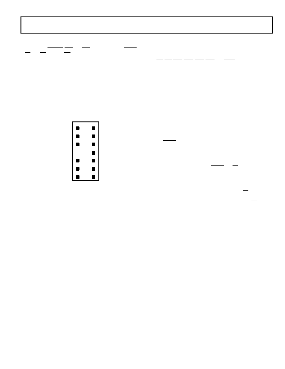
Target Board Connector for EZ-ICE Probe
The EZ-ICE connector (a standard pin strip header) is shown in
Figure 16. This connector must be added to the target board
design to use the EZ-ICE. Be sure to allow enough room in the
system to fit the EZ-ICE probe onto the 14-pin connector.
The 14-pin, 2-row pin strip header is keyed at the Pin 7 loca-
tion—Pin 7 must be removed from the header. The pins must
be 0.025 inch square and at least 0.20 inch in length. Pin spacing
should be 0.1
0.1 inch. The pin strip header must have at least
0.15 inch clearance on all sides to accept the EZ-ICE probe plug.
Pin strip headers are available from vendors such as 3M,
McKenzie, and Samtec.
Target Memory Interface
For the target system to be compatible with the EZ-ICE emula-
tor, it must comply with the following memory interface
guidelines:
Design the Program Memory (PM), Data Memory (DM), Byte
Memory (BM), I/O Memory (IOM), and Composite Memory
(CM) external interfaces to comply with worst-case device
timing requirements and switching characteristics as specified
in this data sheet. The performance of the EZ-ICE may
approach published worst-case specification for some memory
access timing requirements and switching characteristics.
Note:
If the target does not meet the worst-case chip specifica-
tion for memory access parameters, the circuitry may not be
able to be emulated at the desired CLKIN frequency. Depending
on the severity of the specification violation, the system may be
difficult to manufacture, as DSP components statistically vary in
switching characteristic and timing requirements, within pub-
lished limits.
Restriction:
All memory strobe signals on the ADSP-218xN
(RD, WR, PMS, DMS, BMS, CMS, and IOMS) used in the target
system must have 10 kΩ pull-up resistors connected when the
EZ-ICE is being used. The pull-up resistors are necessary
because there are no internal pull-ups to guarantee their state
during prolonged three-state conditions resulting from typical
EZ-ICE debugging sessions. These resistors may be removed
when the EZ-ICE is not being used.
Target System Interface Signals
When the EZ-ICE board is installed, the performance on some
system signals changes. Design the system to be compatible with
the following system interface signal changes introduced by the
EZ-ICE board:
EZ-ICE emulation introduces an 8 ns propagation
delay between the target circuitry and the DSP on the
RESET signal.
EZ-ICE emulation introduces an 8 ns propagation
delay between the target circuitry and the DSP on the BR
signal.
EZ-ICE emulation ignores RESET and BR, when
single-stepping.
EZ-ICE emulation ignores RESET and BR when in Emula-
tor Space (DSP halted).
EZ-ICE emulation ignores the state of target BR in certain
modes. As a result, the target system may take control of
the DSP’s external memory bus only if bus grant (BG) is
asserted by the EZ-ICE board’s DSP.
ADDITIONAL INFORMATION
This data sheet provides a general overview of ADSP-218xN
series functionality. For additional information on the architec-
ture and instruction set of the processor, refer to the ADSP-218x
DSP Hardware Reference and the ADSP-218x DSP Instruction
Set Reference.
Figure 16. Target Board Connector for EZ-ICE
1
2
3
4
56
7
8
910
11
12
13
14
GND
KEY (NO PIN)
RESET
BR
BG
TOP VIEW
EBG
EBR
ELOUT
EE
EINT
ELIN
ECLK
EMS
ERESET
相关PDF资料 |
PDF描述 |
|---|---|
| EBM08DSXN | CONN EDGECARD 16POS DIP .156 SLD |
| RMC35DRXI-S734 | CONN EDGECARD 70POS DIP .100 SLD |
| EBM08DSXH | CONN EDGECARD 16POS DIP .156 SLD |
| HMC31DRXN-S734 | CONN EDGECARD 62POS DIP .100 SLD |
| EEM06DSEI | CONN EDGECARD 12POS .156 EYELET |
相关代理商/技术参数 |
参数描述 |
|---|---|
| ADSP-2185NBSTZ-3202 | 制造商:AD 制造商全称:Analog Devices 功能描述:DSP Microcomputer |
| ADSP-2185NKCA-320 | 功能描述:IC DSP 16BIT 80MHZ 144CSPBGA RoHS:否 类别:集成电路 (IC) >> 嵌入式 - DSP(数字式信号处理器) 系列:ADSP-21xx 标准包装:2 系列:StarCore 类型:SC140 内核 接口:DSI,以太网,RS-232 时钟速率:400MHz 非易失内存:外部 芯片上RAM:1.436MB 电压 - 输入/输出:3.30V 电压 - 核心:1.20V 工作温度:-40°C ~ 105°C 安装类型:表面贴装 封装/外壳:431-BFBGA,FCBGA 供应商设备封装:431-FCPBGA(20x20) 包装:托盘 |
| ADSP-2185NKCAZ-320 | 功能描述:IC DSP 16BIT 80MHZ 144CSPBGA RoHS:是 类别:集成电路 (IC) >> 嵌入式 - DSP(数字式信号处理器) 系列:ADSP-21xx 标准包装:2 系列:StarCore 类型:SC140 内核 接口:DSI,以太网,RS-232 时钟速率:400MHz 非易失内存:外部 芯片上RAM:1.436MB 电压 - 输入/输出:3.30V 电压 - 核心:1.20V 工作温度:-40°C ~ 105°C 安装类型:表面贴装 封装/外壳:431-BFBGA,FCBGA 供应商设备封装:431-FCPBGA(20x20) 包装:托盘 |
| ADSP-2185NKST-320 | 制造商:Analog Devices 功能描述:DSP Fixed-Point 16-Bit 80MHz 80MIPS 100-Pin LQFP 制造商:Rochester Electronics LLC 功能描述:16K PM/16K DM RAM,16-BIT, 80 MIPS, 1.8V - Bulk 制造商:Analog Devices 功能描述:Digital Signal Processor IC Supply Volta |
| ADSP-2185NKSTZ-320 | 功能描述:IC DSP CONTROLLER 16BIT 100LQFP RoHS:是 类别:集成电路 (IC) >> 嵌入式 - DSP(数字式信号处理器) 系列:ADSP-21xx 标准包装:40 系列:TMS320DM64x, DaVinci™ 类型:定点 接口:I²C,McASP,McBSP 时钟速率:400MHz 非易失内存:外部 芯片上RAM:160kB 电压 - 输入/输出:3.30V 电压 - 核心:1.20V 工作温度:0°C ~ 90°C 安装类型:表面贴装 封装/外壳:548-BBGA,FCBGA 供应商设备封装:548-FCBGA(27x27) 包装:托盘 配用:TMDSDMK642-0E-ND - DEVELPER KIT W/NTSC CAMERA296-23038-ND - DSP STARTER KIT FOR TMS320C6416296-23059-ND - FLASHBURN PORTING KIT296-23058-ND - EVAL MODULE FOR DM642TMDSDMK642-ND - DEVELOPER KIT W/NTSC CAMERA |
发布紧急采购,3分钟左右您将得到回复。