参数资料
| 型号: | ADV7343BSTZ |
| 厂商: | Analog Devices Inc |
| 文件页数: | 61/108页 |
| 文件大小: | 0K |
| 描述: | IC ENCODER VIDEO W/DAC 64-LQFP |
| 产品变化通告: | ADV734x, ADV739x Feature Improvement |
| 标准包装: | 1 |
| 类型: | 视频编码器 |
| 应用: | DVD,Blu-Ray |
| 电压 - 电源,模拟: | 3.3V |
| 电压 - 电源,数字: | 1.8V |
| 安装类型: | 表面贴装 |
| 封装/外壳: | 64-LQFP |
| 供应商设备封装: | 64-LQFP(10x10) |
| 包装: | 托盘 |
第1页第2页第3页第4页第5页第6页第7页第8页第9页第10页第11页第12页第13页第14页第15页第16页第17页第18页第19页第20页第21页第22页第23页第24页第25页第26页第27页第28页第29页第30页第31页第32页第33页第34页第35页第36页第37页第38页第39页第40页第41页第42页第43页第44页第45页第46页第47页第48页第49页第50页第51页第52页第53页第54页第55页第56页第57页第58页第59页第60页当前第61页第62页第63页第64页第65页第66页第67页第68页第69页第70页第71页第72页第73页第74页第75页第76页第77页第78页第79页第80页第81页第82页第83页第84页第85页第86页第87页第88页第89页第90页第91页第92页第93页第94页第95页第96页第97页第98页第99页第100页第101页第102页第103页第104页第105页第106页第107页第108页
ADV7342/ADV7343
Data Sheet
Rev. | Page 56 of 108
FILTERS
Table 43 shows an overview of the programmable filters
available on the ADV7342/ADV7343.
Table 43. Selectable Filters
Filter
Subaddress
SD Luma LPF NTSC
0x80
SD Luma LPF PAL
0x80
SD Luma Notch NTSC
0x80
SD Luma Notch PAL
0x80
SD Luma SSAF
0x80
SD Luma CIF
0x80
SD Luma QCIF
0x80
SD Chroma 0.65 MHz
0x80
SD Chroma 1.0 MHz
0x80
SD Chroma 1.3 MHz
0x80
SD Chroma 2.0 MHz
0x80
SD Chroma 3.0 MHz
0x80
SD Chroma CIF
0x80
SD Chroma QCIF
0x80
SD PrPb SSAF
0x82
ED/HD Chroma Input
0x33
ED/HD Sinc Compensation Filter
0x33
ED/HD Chroma SSAF
0x33
SD Internal Filter Response
Subaddress 0x80, Bits[7:2]; Subaddress 0x82, Bit 0
The Y filter supports several different frequency responses,
including two low-pass responses, two notch responses, an
extended (SSAF) response with or without gain boost
attenuation, a CIF response, and a QCIF response. The PrPb
filter supports several different frequency responses, including
six low-pass responses, a CIF response, and a QCIF response, as
shown in Figure 38 and Figure 39.
If SD SSAF gain is enabled (Subaddress 0x87, Bit 4), there are 13
response options in the 4 dB to +4 dB range. The desired response
can be programmed using Subaddress 0xA2. The variation in
frequency responses is shown in Figure 35 to Figure 37.
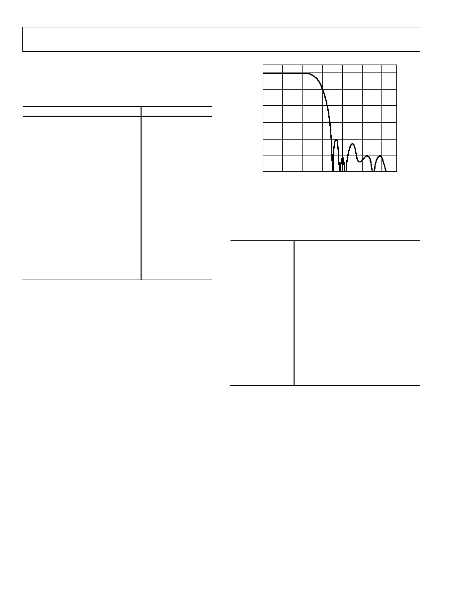
In addition to the chroma filters listed in Table 43, the ADV7342/
ADV7343 contain an SSAF filter that is specifically designed for
the color difference component outputs, Pr and Pb. This filter
has a cutoff frequency of ~2.7 MHz and a gain of –40 dB at 3.8
MHz (see Figure 62). This filter can be controlled with Subaddress
0x82, Bit 0.
FREQUENCY (MHz)
0
G
AI
N
(
d
B)
–10
–30
–50
–60
–20
–40
6
5
4
3
2
1
0
EXTENDED (SSAF) PrPb FILTER MODE
06399-
066
Figure 62. PrPb SSAF Filter
If this filter is disabled, one of the chroma filters shown in
Table 44 can be selected and used for the CVBS or luma/
chroma signal.
Table 44. Internal Filter Specifications
Filter
Pass-Band
Ripple (dB)1
3 dB Bandwidth (MHz)2
Luma LPF NTSC
0.16
4.24
Luma LPF PAL
0.1
4.81
Luma Notch NTSC
0.09
2.3/4.9/6.6
Luma Notch PAL
0.1
3.1/5.6/6.4
Luma SSAF
0.04
6.45
Luma CIF
0.127
3.02
Luma QCIF
Monotonic
1.5
Chroma 0.65 MHz
Monotonic
0.65
Chroma 1.0 MHz
Monotonic
1
Chroma 1.3 MHz
0.09
1.395
Chroma 2.0 MHz
0.048
2.2
Chroma 3.0 MHz
Monotonic
3.2
Chroma CIF
Monotonic
0.65
Chroma QCIF
Monotonic
0.5
1
Pass-band ripple is the maximum fluctuation from the 0 dB response in the
pass band, measured in decibels. The pass band is defined to have 0 Hz to fc
(Hz) frequency limits for a low-pass filter and 0 Hz to f1 (Hz) and f2 (Hz) to
infinity for a notch filter, where fc, f1, and f2 are the 3 dB points.
2
3 dB bandwidth refers to the 3 dB cutoff frequency.
D
相关PDF资料 |
PDF描述 |
|---|---|
| ADV7391BCPZ | IC ENCODER VIDEO W/DAC 32LFCSP |
| ADV7511KSTZ | IC XMITTER HDMI 12BIT 100LQFP |
| ADV7511WBSWZ | IC XMITTER HDMI AUTO 64LQFP |
| ADV7622BSTZ-RL | IC TXRX HDMI 4:1 144LQFP |
| ADV7623BSTZ | IC TXRX HDMI 4:1 144LQFP |
相关代理商/技术参数 |
参数描述 |
|---|---|
| ADV7343WBSTZ | 功能描述:IC ENCODER VID 12BIT DAC 64LQFP 制造商:analog devices inc. 系列:- 包装:托盘 零件状态:在售 类型:视频编码器 应用:DVD,Blu-Ray 电压 - 电源,模拟:2.6 V ~ 3.46 V 电压 - 电源,数字:1.71 V ~ 1.89 V 安装类型:表面贴装 封装/外壳:64-LQFP 供应商器件封装:64-LQFP(10x10) 标准包装:1 |
| ADV7343WBSTZ-RL | 功能描述:Video Encoder IC DVD, Blu-Ray 64-LQFP (10x10) 制造商:analog devices inc. 系列:- 包装:带卷(TR) 零件状态:有效 类型:视频编码器 应用:DVD,Blu-Ray 电压 - 电源,模拟:2.6 V ~ 3.46 V 电压 - 电源,数字:1.71 V ~ 1.89 V 安装类型:表面贴装 封装/外壳:64-LQFP 供应商器件封装:64-LQFP(10x10) 标准包装:1,500 |
| ADV7344 | 制造商:AD 制造商全称:Analog Devices 功能描述:Multiformat Video Encoder Six 14-Bit Noise Shaped Video DACs |
| ADV7344BSTZ | 制造商:Analog Devices 功能描述: |
| ADV73505501 | 制造商:LG Corporation 功能描述:Frame Assembly |
发布紧急采购,3分钟左右您将得到回复。