- 您现在的位置:买卖IC网 > PDF目录378403 > AN1042 (ON SEMICONDUCTOR) High Fidelity Switching Audio Amplifiers Using TMOS Power MOSFETs PDF资料下载
参数资料
| 型号: | AN1042 |
| 厂商: | ON SEMICONDUCTOR |
| 英文描述: | High Fidelity Switching Audio Amplifiers Using TMOS Power MOSFETs |
| 中文描述: | 高保真开关音频放大器使用的TMOS功率MOSFET |
| 文件页数: | 7/12页 |
| 文件大小: | 108K |
| 代理商: | AN1042 |
AN1042/D
http://onsemi.com
7
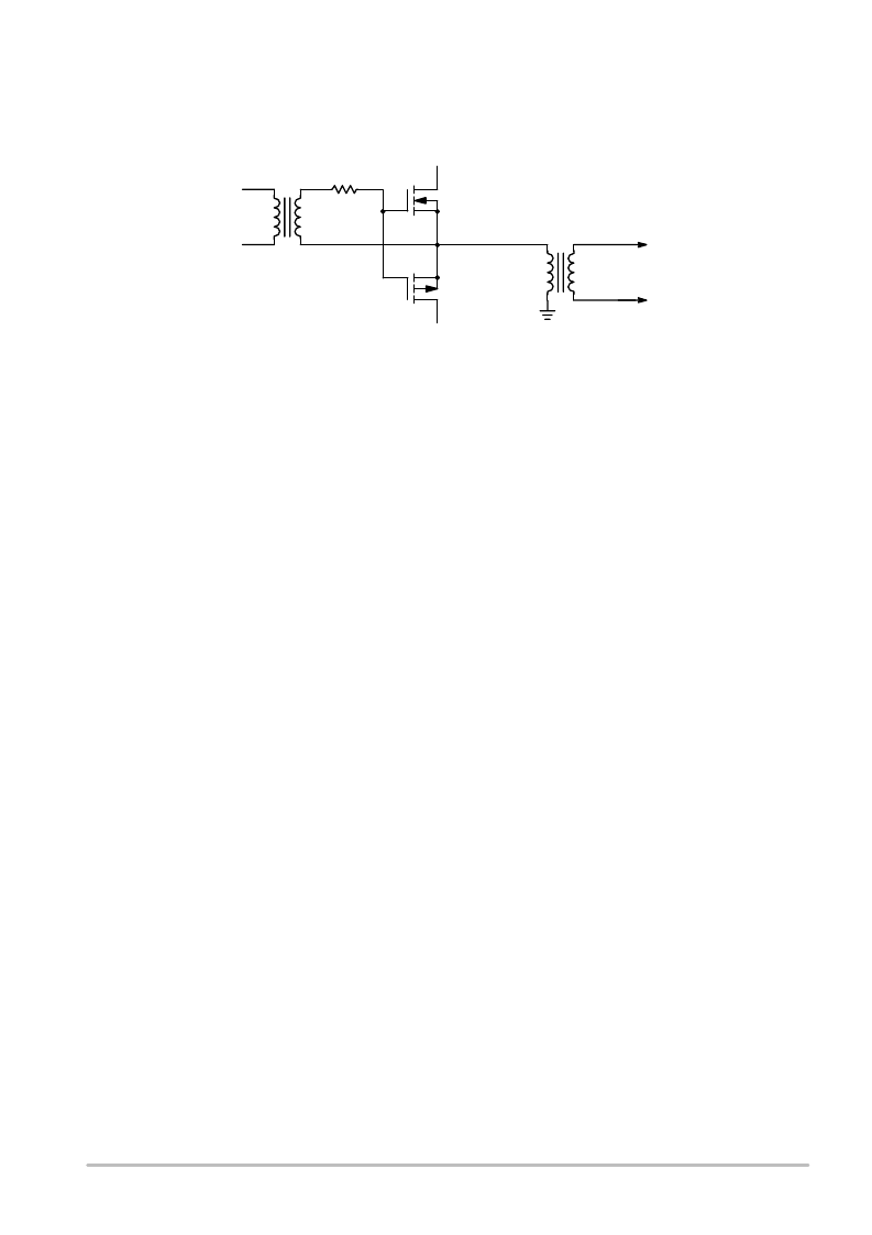
Figure 11. Voltage Balance Circuit
+44
Q6
Q5
–44
R34
20 kHz
+8 V Drive
T1
33T
#16
Litz
8T
#20
±
5 V
Power
100
μ
hy
One means of coupling the positive and negative
supplies that has been used successfully by the author is
shown in Figure 11. A complementary pair of TMOS power
MOSFETs is driven by a square wave at 20 kHz. This drive
signal was obtained from the switching power supply used
with the amplifier. If lower efficiency is acceptable, the
120 kHz switching amplifier frequency may be used
instead. The Ferroxcube E core is gapped to allow a large
current without saturation. its primary inductance is 100
microhenries and the primary current is a triangle of
±
5.5
amps. Any mismatch in the two supply voltages will result
in a net average dc component on the square wave going to
the primary. A direct current of 3.5 amps can be added to
the 11 amp peak to peak triangle before reaching the 9 amp
saturation level.
If the +44 volt supply is high, extra energy will be stored
in the primary of T1 during the on time of Q5. When Q5 is
turned off and Q6 is turned on, the energy is transferred
from the primary of T1 through Q6 to the –44 volt supply.
The net effect is that the +44 volt buss is reduced in voltage
and the –44 volt buss is increased. This restores the balance
between the two supplies. If the –44 volt supply is too high,
the operation is similar with the roles of Q5 and Q6
reversed. It is important to use Litz wire for the primary of
T1 because of the large high frequency component of
primary current. An 8 turn secondary winding can be used
to generate
±
11 volts for powering
±
5 volt regulators for the
switching amp. If that is done, the amp will not operate
unless the voltage balance circuit is working properly. This
is a very important safety feature, since the amplifier can
be destroyed if the supply voltages run away.
The losses in the switching amplifier are attributable to
on resistance, switching times, diode recovery spikes and
the output filter. Diode recovery losses dominate all these
losses. The new improved E series devices will greatly
reduce these losses because their recovery times are about
one fourth as long.
At low frequencies, the principal loss in the output filter
is the winding resistance. See Figure 5. The winding
resistance is on the order of 40 milliohms which causes a
loss of about 0.5%. At 20 kHz, this rises to about 2% due
to skin effect. If Litz wire is not used, losses can easily
reach 5%. Capacitor losses in the output filter are
negligible if multilayer film capacitors are used. The
inductors used in the filter must tolerate well over 5 amps
of dc without saturation and have very low hysteresis loss.
Molypermalloy cores were used first for output filter
inductors but their losses were too high. They exhibited
third harmonic distortion of 5% in the 5 kHz region as well
as severe heating when passing high frequencies. These
problems were caused by their excessive hysteresis.
Gapped ferrites wound with #14 solid magnet wire were
next used. They cured the high frequency heating and
distortion problems. However, the high frequency –3 dB
point was 17 kHz instead of the theoretical 20 kHz. This
was found to be due to skin effect losses in the windings.
Use of #16 Litz wire raised the high frequency cutoff point
to 19.5 kHz.
The input inductor must handle 120 kHz triangle current
of
±
0.8 amp during no signal conditions. The loss is about
0.1 watt due to this triangle. The input inductor has 31 turns
and saturates at about 10 amps. The output inductor has
only 26 turns and saturates at about 12 amps. These currents
are well above the 5 amp current limit of the amplifier and
insure that the inductors will remain linear. Inductors for
higher power filters must use larger cores with appropriate
gaps to avoid saturation. Higher voltage capacitors must
also be used.
Capacitors used in the filter must have a Q in excess of
100 at 20 kHz and must be nonpolarized. Multilayer film
capacitors with a rating of 63 volts dc have been used
successfully. If the filter is unloaded and the amplifier is
operated in the vicinity of one of its parallel resonance
points, excessive voltages will be generated. This problem
is most severe at 11.4 kHz. Only 1 volt out of the amplifier
under normal conditions will generate 60 volts at the
junction of the filter inductors when the output is
unterminated. Several amps of current will be generated in
the inductors as well, possibly resulting in their saturation.
Such high frequency operation can lead to failure of
capacitors in the filter and destruction of output switching
transistors. The filter may be open circuited with music or
speech without damage, since little continuous power
exists at the 11.4 kHz resonance point.
Good RF layout practices must be used in construction
of the filter. The winding end closest to the core should be
相关PDF资料 |
PDF描述 |
|---|---|
| AN1042D | High Fidelity Switching Audio Amplifiers Using TMOS Power MOSFETs |
| AN1062 | Circular Connector; No. of Contacts:6; Series:MS27508; Body Material:Aluminum; Connecting Termination:Crimp; Connector Shell Size:8; Circular Contact Gender:Socket; Circular Shell Style:Box Mount Receptacle; Insert Arrangement:8-35 RoHS Compliant: No |
| AN1077 | ISL6244EVAL1 Multi-phase Evaluation Board Setup Procedure |
| AN1082 | Using the ISL6401 RSLIC PWM Controller Evaluation Board |
| AN1406 | DESIGNING WITH PECL (ECL AT + 5.0) |
相关代理商/技术参数 |
参数描述 |
|---|---|
| AN-1042 | 制造商:CYMBET 制造商全称:CYMBET 功能描述:EnerChip CC Backup Power for Epson RX-8564 Real-Time Clock |
| AN1042D | 制造商:ONSEMI 制造商全称:ON Semiconductor 功能描述:High Fidelity Switching Audio Amplifiers Using TMOS Power MOSFETs |
| AN1043 | 制造商:MICROCHIP 制造商全称:Microchip Technology 功能描述:Unique Features of the MCP23X08/17 GPIO Expanders |
| AN-1043 | 制造商:CYMBET 制造商全称:CYMBET 功能描述:EnerChip CC as Backup Power for a DS1390 Real-Time Clock |
| AN10436 | 制造商:PHILIPS 制造商全称:NXP Semiconductors 功能描述:TDA8932B/33(B) Class-D audio amplifier |
发布紧急采购,3分钟左右您将得到回复。