- 您现在的位置:买卖IC网 > PDF目录378403 > AN1042 (ON SEMICONDUCTOR) High Fidelity Switching Audio Amplifiers Using TMOS Power MOSFETs PDF资料下载
参数资料
| 型号: | AN1042 |
| 厂商: | ON SEMICONDUCTOR |
| 英文描述: | High Fidelity Switching Audio Amplifiers Using TMOS Power MOSFETs |
| 中文描述: | 高保真开关音频放大器使用的TMOS功率MOSFET |
| 文件页数: | 8/12页 |
| 文件大小: | 108K |
| 代理商: | AN1042 |
AN1042/D
http://onsemi.com
8
used as the input on both inductors. This will provide a
measure of shielding against capacitively coupled RFI.
The cores and the current sense resistor R27 should be
grounded to the same point as the power supply grounds of
the output switching transistors. The lead for the input
inductor that connects to the switching transistors must be
as short as possible to minimize RFI.
The on–resistance of the MTP12N210/12P10 is rated at
0.18 and 0.3 ohms maximum respectively. We will assume
that 5 amps is being switched by the two devices. In that
case the N channel will dissipate 4.5 watts and the P
channel will dissipate 7.5 watts.
At forward currents of 5 amps, the source drain voltage
of the N channel will be 0.9 volts and the P channel will be
1.5 volts. If this current is reversed, the drop will be high
enough to activate the source drain diode. This will occur
for reverse currents of about 3 and 2 amps for the N and P
channel devices respectively. Charge stored in the source
drain diode causes recovery current spikes when the
opposite device turns on. These spikes are the main cause
of heating in the switching devices. On resistance losses are
somewhat less than expected on the basis of drain
resistance calculations because of the voltage clamping
effect of the source drain diode during reverse current.
The approximate combined output capacitance of the N
and P channel is about 700 pF. Charging and discharging
this capacitance takes energy. At
±
44 volt supply voltages
and 120 kHz, this amounts to about 0.3 watts in each
device. This loss is the least significant of the various
losses.
When reverse current flows through the source–drain
diode, a charge is stored in the form of minority carriers in
the junction. When the opposite switch turns on, this diode
acts as a momentary short until these carriers are
recombined. This short exists for about 0.1 microsecond
for the N channel and slightly less for the P channel. During
this time, the opposite switch will be conducting a current
of about 12 amps in an attempt to clear out the carriers
stored by the previous 5 amp current. The 88 volts across
the switch during this time causes a peak dissipation of
1056 watts. The average power during the 120 kHz
switching cycle will be 10 watts for the N channel and 12
watts for the P channel.
Diode recovery losses dwarf all other losses. When the
switching devices get hot, their diode storage time
increases This aggravates the problem and can lead to
thermal runaway. The increase in loss with temperature can
be mistaken for on resistance increase. Remember that a
slow diode heats the opposite switch. The P channel
therefore takes the blame for the slower N channel diode.
The short high current pulses cause troublesome spikes on
power supply busses and generate RFI. The author has
found dramatic differences in the recovery times of power
MOSFETs from various manufacturers. In several cases,
devices of lower on resistance caused much higher losses
in the opposite switch due to their slower diodes.
When we add all losses, we get a total of 14.8 watts for
the N channel and 19.8 watts for the P channel. The normal
conditions of 50% duty cycle for each device gives losses
of 7.5 and 10 watts respectively. To avoid overheating,
short circuits must be limited to 5 minutes. With normal
sine wave output of 72 watts, the N channel dissipates 2
watts and the P channel dissipated 3 watts. Heatsinks used
must limit the temperature of the switching devices at 80
°
C
to prevent thermal runaway caused by increased diode
recovery losses.
The three components of switching loss are drain
resistance, drain capacitance and diode recovery. Drain
resistance loss varies only as the square of the current.
Drain capacitance loss varies as the product of the drain
capacitance, the square of the supply voltages, and the
switching frequency. Diode recovery loss varies as the
product of the supply voltage, switching frequency, and
diode recovery time. Rise time has little effect on diode
recovery loss. The best way to reduce losses is with the new
E series TMOS with improved source drain diodes. The
only other way to reduce loss is to lower the switching
frequency. Lower on resistance will have only a small
effect on overall loss.
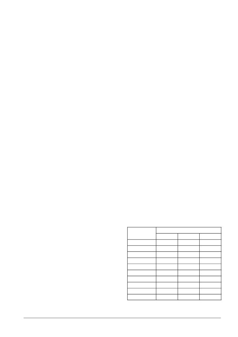
It is desirable to switch at the lowest possible frequency
in order to reduce losses in the output devices. On the other
hand, low frequencies can introduce 2nd harmonic
distortion in the the signal and complicate the output filter
design. Tables 1 and 2 show the spectrum of the output of
a switching amplifier before the filter as derived by Fourier
analysis. The spectrum shown is for a sine wave of various
levels of 20 kHz output for carriers of 80 and 100 kHz. Note
that the 100 kHz carrier generates no even harmonics. The
80 kHz carrier generates a substantial amount of even
harmonics.
Table 1. Frequency Spectrum of Switching Amplifier
Carrier Frequency = 80 kHz with 20 kHz Sine Wave Modulation
Harmonic
Number
Percent of Rated Power
100%
50%
25%
Fundamental
0.981
0.498
0.250
2
0.186
0.048
0.012
3
0.052
0.007
0.001
4
0.600
1.084
1.224
5
0.118
0.018
0.002
6
0.362
0.130
0.035
7
0.309
0.390
0.235
8
0.192
0.017
0
9
0.065
0.328
0.226
10
0.217
0.176
0.056
相关PDF资料 |
PDF描述 |
|---|---|
| AN1042D | High Fidelity Switching Audio Amplifiers Using TMOS Power MOSFETs |
| AN1062 | Circular Connector; No. of Contacts:6; Series:MS27508; Body Material:Aluminum; Connecting Termination:Crimp; Connector Shell Size:8; Circular Contact Gender:Socket; Circular Shell Style:Box Mount Receptacle; Insert Arrangement:8-35 RoHS Compliant: No |
| AN1077 | ISL6244EVAL1 Multi-phase Evaluation Board Setup Procedure |
| AN1082 | Using the ISL6401 RSLIC PWM Controller Evaluation Board |
| AN1406 | DESIGNING WITH PECL (ECL AT + 5.0) |
相关代理商/技术参数 |
参数描述 |
|---|---|
| AN-1042 | 制造商:CYMBET 制造商全称:CYMBET 功能描述:EnerChip CC Backup Power for Epson RX-8564 Real-Time Clock |
| AN1042D | 制造商:ONSEMI 制造商全称:ON Semiconductor 功能描述:High Fidelity Switching Audio Amplifiers Using TMOS Power MOSFETs |
| AN1043 | 制造商:MICROCHIP 制造商全称:Microchip Technology 功能描述:Unique Features of the MCP23X08/17 GPIO Expanders |
| AN-1043 | 制造商:CYMBET 制造商全称:CYMBET 功能描述:EnerChip CC as Backup Power for a DS1390 Real-Time Clock |
| AN10436 | 制造商:PHILIPS 制造商全称:NXP Semiconductors 功能描述:TDA8932B/33(B) Class-D audio amplifier |
发布紧急采购,3分钟左右您将得到回复。