- 您现在的位置:买卖IC网 > PDF目录378403 > AN1593 (Motorola, Inc.) LOW COST 1.0 A CURRENT SOURCE FOR BATTERY CHARGERS PDF资料下载
参数资料
| 型号: | AN1593 |
| 厂商: | Motorola, Inc. |
| 元件分类: | 基准电压源/电流源 |
| 英文描述: | LOW COST 1.0 A CURRENT SOURCE FOR BATTERY CHARGERS |
| 中文描述: | 低成本1.0电流源的电池充电器 |
| 文件页数: | 2/8页 |
| 文件大小: | 212K |
| 代理商: | AN1593 |
2
MOTOROLA ANALOG IC APPLICATIONS INFORMATION
(‘c’ rate) up until the charge limit is reached. After that, the
battery has to be charged by a much lower current at the so
called ‘trickle charge’ rate. Trickle charging is a continuous
low current charging rate that keeps the battery fully charged.
While NiCd batteries have a recommended trickle charge
rate of about c/10, for NiMH type it is not recommended to
exceed a charging rate of c/40.
Some battery manufacturers recommend, for their
chemistry, pulse charging instead of continuous current
charging. This feature can be accomplished by use of the
ON/OFF pin of the LM2575.
Circuit Operation
Circuit operation is as follows. When a discharged battery
is connected to the charger, the circuit operates as a constant
current source. The LM2575–ADJ buck regulator is used to
step down an unregulated dc input voltage. This regulator is
capable of providing up to 1.0 A of charging current.The
amount of charging current flowing into the battery is
controlled by the MC33341 regulation control circuit. This IC
is used to control the feedback loop in either
constant–current or constant–voltage mode with automatic
crossover. The MC33341 features the unique ability to
perform both high–side and low–side current sensing, each
with either internally fixed or externally adjustable threshold
level. This feature makes this circuit very universal and
ideally suited for use in connection with a microcontroller
based intelligent control systems.
In the circuit shown in Figure 2,the MC33341 control
circuit is configured for high–side current sensing. The
voltage drop across the sense resistor RS provides a voltage
that is proportional to the charging current. The current
regulation threshold V
sen
can be adjusted externally (switch
S1 in position “2”) in the range of 0 V to 200 mV with respect
to Pin 4 of U2. When the switch S1 is in position “1”, the
current regulation threshold level is set internally to 200 mV.
Then the regulated current can be calculated as follows:
Ireg
Vsen
RS
0.2
RS
Resistor R3 is required in those applications where a high
peak level of reverse current is possible, if the source outputs
are shorted and the diode D2 is not used. The resistor value
should be chosen to limit the input current of the internal VCC
clamp diode to less than 20 mA. Excessively large values for
R3 will degrade the current sensing accuracy. Resistor R3
value can be calculated from the following expression:
R3
IpkRS– 0.6
0.02
where IpkRS is a peak current flowing through the sense
resistor RS.
Once the battery voltage reaches a predetermined level,
the MC33341 begins to regulate in the constant–voltage
mode and the charger starts to regulate the voltage across
the battery. This voltage is monitored by Pin 5 of U2, the
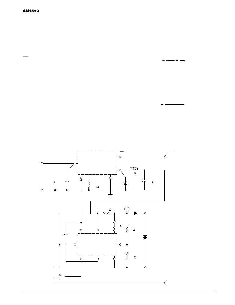
Figure 2. Low Cost Switching Regulator Performs
Constant–Current/Constant–Voltage 3 Cell Charging Function
R4
1.0 k
L1
400 H
D1
1N5819
C2
330 F/16 V
ON/OFF
Control
(from Controller)
+
+
+Vin
ON/OFF
Unregulated
DC – Input
Vin = 10 to 40 V
R3
27
6
R2
39
R1
10 k
C3
33 nF
RS
0.22
3 Battery Cells
Under Charge
Charge Current
Control
(from Controller)
–VO
+VO
1N4001
+
–
+
Gnd
U1
LM2575–ADJ
U2
MC33341
Gnd
C1
100 F/50 V
Feedback
Output
1
2
4
5
3
D2
1
2
4
5
3
7
8
S1
1
2
A
相关PDF资料 |
PDF描述 |
|---|---|
| AN1607 | ITC122 low voltage micro to motor interface |
| AN1672 | The ECL Translator Guide |
| AN1672D | The ECL Translator Guide |
| AN1687 | A FULL-FEATURED WIRELESS INTERFACE FOR RS-232 COMMUNICATIONS |
| AN1812 | Freescale Semiconductor, Inc. |
相关代理商/技术参数 |
参数描述 |
|---|---|
| AN15931A-E1 | 制造商:Panasonic Industrial Company 功能描述:IC |
| AN15-C08 | 制造商:SMC Corporation of America 功能描述:Silencer, Compact Resin, One-Touch, 8mm Port, 30 dB(A), 45mm, Model AN15-C08 制造商:SMC 功能描述:Compact silencer Resin 8mm push in male 制造商:SMC 功能描述:SY3000 silencer, compact resin type () |
| AN15-N02 | 制造商:SMC Corporation of America 功能描述:Silencer, Airline, 1/4NPT Port |
| AN-16 | 制造商:未知厂家 制造商全称:未知厂家 功能描述:TOPSwitch Flyback Design Methodology |
| AN1603-433 | 制造商:未知厂家 制造商全称:未知厂家 功能描述:陶瓷天线 Multilayer Chip Antenna for 433MHz Wireless Communication |
发布紧急采购,3分钟左右您将得到回复。