- 您现在的位置:买卖IC网 > PDF目录255362 > AS2320-9RD3TB1 2-OUTPUT 100 W DC-DC REG PWR SUPPLY MODULE PDF资料下载
参数资料
| 型号: | AS2320-9RD3TB1 |
| 元件分类: | 电源模块 |
| 英文描述: | 2-OUTPUT 100 W DC-DC REG PWR SUPPLY MODULE |
| 封装: | METAL, CASE S02, MODULE |
| 文件页数: | 15/31页 |
| 文件大小: | 633K |
| 代理商: | AS2320-9RD3TB1 |
第1页第2页第3页第4页第5页第6页第7页第8页第9页第10页第11页第12页第13页第14页当前第15页第16页第17页第18页第19页第20页第21页第22页第23页第24页第25页第26页第27页第28页第29页第30页第31页
Cassette Style
100 Watt DC-DC Converters
S Series
Edition 1/01.2000
22/31
Installation Instructions
The S series DC-DC converters are components, intended
exclusively for inclusion within other equipment by an in-
dustrial assembly operation or by professional installers.
Installation must strictly follow the national safety regula-
tions
in
compliance
with
the
enclosure,
mounting,
creepage, clearance, casualty, markings and segregation
requirements of the end-use application.
Connection to the system shall be made via the female
connector H15 (see:
Accessories). Other installation meth-
ods may not meet the safety requirements.
The DC-DC converters are provided with pin no. 24 ( ),
which is reliably connected with their case. For safety rea-
sons it is essential to connect this pin with the protective
earth of the supply system unless specified in:
Safety of op-
erator accessible output circuit.
An input fuse is built-in in the connection from pins no. 30
and 32 (Vi-) of the unit. Since this fuse is designed to pro-
tect the unit in case of an overcurrent and does not neces-
sarily cover all customer needs, an external fuse suitable
for the application and in compliance with the local require-
ments might be necessary in the wiring to one or both input
potentials, pins nos. 26 and 28 and/or nos. 30 and 32.
Important: Whenever the inhibit function is not in use,
pin no. 18 (i) should be connected to pin no. 14 (S–/
Vo1–) to enable the output(s).
Do not open the modules, or guarantee will be invali-
dated.
Due to high current values, all AS...ES units provide two in-
ternally parallel connected contacts for certain paths (pins
4/6, 8/10, 26/28 and 30/32, respectively). It is recommen-
ded to connect load and supply to both female connector
pins of each path in order to keep the voltage drop across
the connector pins to an absolute minimum and to not
overstress the connector contacts if currents are higher
than approx. 8 A. The connector contacts are rated 8 A over
the whole temperature range.
Make sure that there is sufficient air flow available for con-
vection cooling. This should be verified by measuring the
case temperature when the unit is installed and operated in
the end-use application. The maximum specified case tem-
perature
TC max shall not be exceeded. See also: Thermal
Considerations.
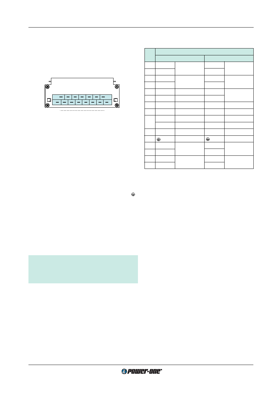
Fig. 23
View of module’s male H15 connector
Safety and Installation Instructions
Connector Pin Allocation
The connector pin allocation table defines the electrical
potentials and the physical pin positions on the H15 con-
nector. Pin no. 24, the protective earth pin present on all
AS…ES DC-DC converters is leading, ensuring that it
makes contact with the female connector first.
If the end-product is to be UL certified, the temperature of
the main isolation transformer should be evaluated as part
of the end-product investigation.
Check for hazardous voltages before altering any connec-
tions.
Ensure that a unit failure (e.g. by an internal short-circuit)
does not result in a hazardous condition. See also:
Safety
of operator accessible output circuit.
Cleaning Agents
In order to avoid possible damage, any penetration of
cleaning fluids is to be prevented, since the power supplies
are not hermetically sealed.
Standards and Approvals
All DC-DC converters correspond to class I equipment.
They are UL recognized according to UL 1950, UL recog-
nized for Canada to CAN/CSA C22.2 No. 950-95 and LGA
approved to IEC/EN 60950 standards.
The units have been evaluated for:
Building in
Basic insulation between input and case and double or
reinforced insulation between input and output, based
on 150 V AC and DC (AS and BS) or 250 V AC and
400 V DC (CS, DS, ES, FS)
The use in a pollution degree 2 environment
Connecting the input to a primary or secondary circuit
which is subject to a maximum transient rating of
2500 V
The DC-DC converters are subject to manufacturing sur-
veillance in accordance with the above mentioned UL,
CSA, EN and with ISO 9001 standards.
4
32
Type H15
10002
Table 12: Pin allocation of the H15 connector
Pin
Connector type H 15
No.
AS...ES 1000
AS...ES 2000
4
Vo1+
Output 1
Vo2+
Output 2
6
Vo1+
Vo2+
8Vo1–
Output 1
Vo2–
Output 2
10
Vo1–
Vo2–
12
S+
Sense
Vo1+
Output 1
14
S–
Sense
Vo1–
16
R 1
Control of
U o1
R 1
Control of
U o1
18
i
Inhibit
i
Inhibit
20
D 3
Save data
D
Save data
V 3
ACFAIL
22
T
Current sharing T
Current sharing
24 2
Protective earth
26
Vi+
Input
Vi+
Input
28
Vi+
30
Vi–
Input
Vi–
Input
32
Vi–
1 Feature R excludes option P and vice versa.
2 Leading pin (pre-connecting).
3 Option D excludes option V and vice versa.
相关PDF资料 |
PDF描述 |
|---|---|
| AS2320-9RD5B2 | 2-OUTPUT 100 W DC-DC REG PWR SUPPLY MODULE |
| AS2540-9PD8TB1 | 2-OUTPUT 100 W DC-DC REG PWR SUPPLY MODULE |
| AS2660-7PD8TB1 | 2-OUTPUT 100 W DC-DC REG PWR SUPPLY MODULE |
| AS2660-7RD3B2 | 2-OUTPUT 100 W DC-DC REG PWR SUPPLY MODULE |
| AM1501-7PV2F | 1-OUTPUT 50 W DC-DC REG PWR SUPPLY MODULE |
相关代理商/技术参数 |
参数描述 |
|---|---|
| AS23240FLF | 制造商:TT Electronics / IRC 功能描述:AS23240FLF |
| AS23240HLF | 制造商:TT Electronics / IRC 功能描述:AS23240HLF |
| AS23240JLF | 制造商:TT Electronics / IRC 功能描述:AS23240JLF |
| AS23241FLF | 制造商:TT Electronics / IRC 功能描述:AS23241FLF |
| AS23241HLF | 制造商:TT Electronics / IRC 功能描述:AS23241HLF |
发布紧急采购,3分钟左右您将得到回复。