参数资料
| 型号: | AT25010N-10SI-2.7 |
| 厂商: | Atmel |
| 文件页数: | 7/17页 |
| 文件大小: | 0K |
| 描述: | IC EEPROM 1KBIT 2.1MHZ 8SOIC |
| 标准包装: | 100 |
| 格式 - 存储器: | EEPROMs - 串行 |
| 存储器类型: | EEPROM |
| 存储容量: | 1K (128 x 8) |
| 速度: | 2.1MHz |
| 接口: | SPI 3 线串行 |
| 电源电压: | 2.7 V ~ 5.5 V |
| 工作温度: | -40°C ~ 85°C |
| 封装/外壳: | 8-SOIC(0.154",3.90mm 宽) |
| 供应商设备封装: | 8-SOIC |
| 包装: | 管件 |
�� �
�
�AT25010/020/040�
�WRITE� ENABLE� (WREN):� The� device� will� power� up� in� the� write� disable� state� when� V� CC�
�is� applied.� All� programming� instructions� must� therefore� be� preceded� by� a� Write� Enable�
�instruction.� The� WP� pin� must� be� held� high� during� a� WREN� instruction.�
�WRITE� DISABLE� (WRDI):� To� protect� the� device� against� inadvertent� writes,� the� Write�
�Disable� instruction� disables� all� programming� modes.� The� WRDI� instruction� is� indepen-�
�dent� of� the� status� of� the� WP� pin.�
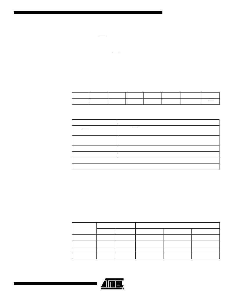
�READ� STATUS� REGISTER� (RDSR):� The� Read� Status� Register� instruction� provides�
�access� to� the� status� register.� The� READY/BUSY� and� Write� Enable� status� of� the� device�
�can� be� determined� by� the� RDSR� instruction.� Similarly,� the� Block� Write� Protection� bits�
�indicate� the� extent� of� protection� employed.� These� bits� are� set� by� using� the� WRSR�
�instruction.�
�Table� 2.� Status� Register� Format�
�Bit� 7�
�X�
�Bit� 6�
�X�
�Bit� 5�
�X�
�Bit� 4�
�X�
�Bit� 3�
�BP1�
�Bit� 2�
�BP0�
�Bit� 1�
�WEN�
�Bit� 0�
�RDY�
�Table� 3.� Read� Status� Register� Bit� Definition�
�Bit�
�Bit� 0� (RDY)�
�Bit� 1� (WEN)�
�Bit� 2� (BP0)�
�Bit� 3� (BP1)�
�Definition�
�Bit� 0� =� 0� (RDY)� indicates� the� device� is� READY.� Bit� 0� =� 1� indicates� the�
�write� cycle� is� in� progress.�
�Bit� 1� =� 0� indicates� the� device� is� not� WRITE� ENABLED.� Bit� 1� =� 1� indicates�
�the� device� is� WRITE� ENABLED.�
�See� Table� 4.�
�See� Table� 4.�
�Bits� 4-7� are� 0s� when� device� is� not� in� an� internal� write� cycle.�
�Bits� 0-7� are� 1s� during� an� internal� write� cycle.�
�WRITE� STATUS� REGISTER� (WRSR):� The� WRSR� instruction� allows� the� user� to� select�
�one� of� four� levels� of� protection.� The� AT25010/020/040� is� divided� into� four� array� seg-�
�ments.� Top� quarter� (1/4),� Top� half� (1/2),� or� all� of� the� memory� segments� can� be�
�protected.� Any� of� the� data� within� any� selected� segment� will� therefore� be� READ� only.� The�
�block� write� protection� levels� and� corresponding� status� register� control� bits� are� shown� in�
�Table� 4.�
�The� two� bits,� BP1� and� BP0� are� nonvolatile� cells� that� have� the� same� properties� and� func-�
�tions� as� the� regular� memory� cells� (e.g.� WREN,� t� WC� ,� RDSR).�
�Table� 4.� Block� Write� Protect� Bits�
�Status� Register� Bits�
�Array� Addresses� Protected�
�Level�
�0�
�1� (1/4)�
�2� (1/2)�
�3� (All)�
�BP1�
�0�
�0�
�1�
�1�
�BP0�
�0�
�1�
�0�
�1�
�AT25010�
�None�
�60-7F�
�40-7F�
�00-7F�
�AT25020�
�None�
�C0-FF�
�80-FF�
�00-FF�
�AT25040�
�None�
�180-1FF�
�100-1FF�
�000-1FF�
�7�
�0606M–SEEPR–06/03�
�相关PDF资料 |
PDF描述 |
|---|---|
| SOMAM3703-10-2780HFCR | SYSTEM ON MODULE LV AM3703 |
| AT25010-10PI-2.7 | IC EEPROM 1KBIT 2.1MHZ 8DIP |
| AT24C64W-10SI-2.7 | IC EEPROM 64KBIT 400KHZ 8SOIC |
| AT24C64N-10SI-2.7 | IC EEPROM 64KBIT 400KHZ 8SOIC |
| AT24C64-10PI-2.7 | IC EEPROM 64KBIT 400KHZ 8DIP |
相关代理商/技术参数 |
参数描述 |
|---|---|
| AT25010Y1-10YI-2.7 | 制造商:未知厂家 制造商全称:未知厂家 功能描述:EEPROM |
| AT25010Y2-10YI-2.7 | 制造商:未知厂家 制造商全称:未知厂家 功能描述:EEPROM |
| AT25016-0T3X | 制造商:Atmel Corporation 功能描述: |
| AT25020 | 制造商:ATMEL 制造商全称:ATMEL Corporation 功能描述:SPI Serial EEPROMs |
| AT25020-10PA-2.7C | 制造商:未知厂家 制造商全称:未知厂家 功能描述:SERIAL EEPROM|256X8|CMOS|DIP|8PIN|PLASTIC |
发布紧急采购,3分钟左右您将得到回复。