参数资料
| 型号: | AT89C51AC3-RLTIM |
| 厂商: | Atmel |
| 文件页数: | 122/140页 |
| 文件大小: | 0K |
| 描述: | IC 8051 MCU FLASH 64K 44VQFP |
| 标准包装: | 160 |
| 系列: | 89C |
| 核心处理器: | 8051 |
| 芯体尺寸: | 8-位 |
| 速度: | 60MHz |
| 连通性: | UART/USART |
| 外围设备: | POR,PWM,WDT |
| 输入/输出数: | 36 |
| 程序存储器容量: | 64KB(64K x 8) |
| 程序存储器类型: | 闪存 |
| EEPROM 大小: | 2K x 8 |
| RAM 容量: | 2.25K x 8 |
| 电压 - 电源 (Vcc/Vdd): | 3 V ~ 5.5 V |
| 数据转换器: | A/D 8x10b |
| 振荡器型: | 外部 |
| 工作温度: | -40°C ~ 85°C |
| 封装/外壳: | 44-LQFP |
| 包装: | 托盘 |
第1页第2页第3页第4页第5页第6页第7页第8页第9页第10页第11页第12页第13页第14页第15页第16页第17页第18页第19页第20页第21页第22页第23页第24页第25页第26页第27页第28页第29页第30页第31页第32页第33页第34页第35页第36页第37页第38页第39页第40页第41页第42页第43页第44页第45页第46页第47页第48页第49页第50页第51页第52页第53页第54页第55页第56页第57页第58页第59页第60页第61页第62页第63页第64页第65页第66页第67页第68页第69页第70页第71页第72页第73页第74页第75页第76页第77页第78页第79页第80页第81页第82页第83页第84页第85页第86页第87页第88页第89页第90页第91页第92页第93页第94页第95页第96页第97页第98页第99页第100页第101页第102页第103页第104页第105页第106页第107页第108页第109页第110页第111页第112页第113页第114页第115页第116页第117页第118页第119页第120页第121页当前第122页第123页第124页第125页第126页第127页第128页第129页第130页第131页第132页第133页第134页第135页第136页第137页第138页第139页第140页
dsPIC33FJXXXGPX06/X08/X10
DS70286C-page 80
2009 Microchip Technology Inc.
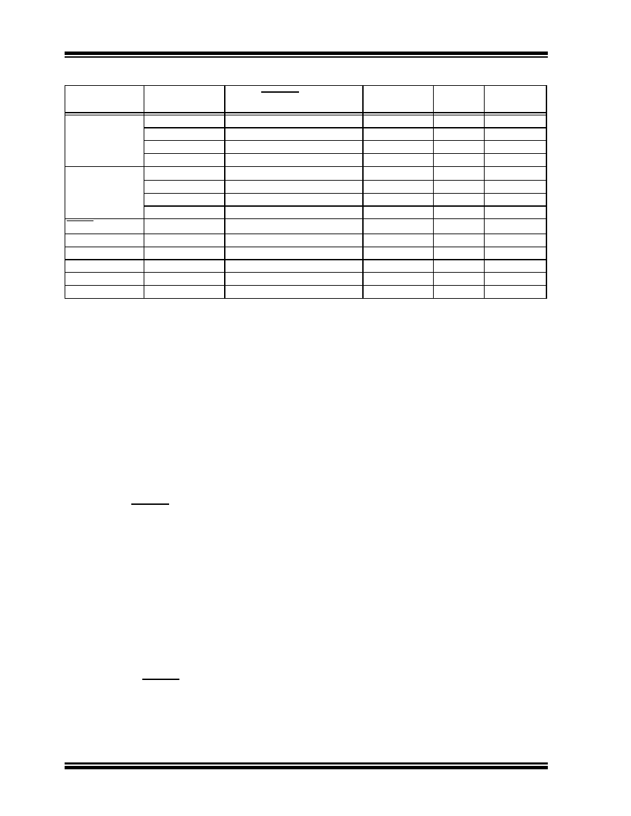
TABLE 6-3:
RESET DELAY TIMES FOR VARIOUS DEVICE RESETS
6.2.1
POR AND LONG OSCILLATOR
START-UP TIMES
The oscillator start-up circuitry and its associated delay
timers are not linked to the device Reset delays that
occur at power-up. Some crystal circuits (especially
low-frequency crystals) have a relatively long start-up
time. Therefore, one or more of the following conditions
is possible after SYSRST is released:
The oscillator circuit has not begun to oscillate.
The Oscillator Start-up Timer has not expired (if a
crystal oscillator is used).
The PLL has not achieved a lock (if PLL is used).
The device will not begin to execute code until a valid
clock source has been released to the system.
Therefore, the oscillator and PLL start-up delays must
be considered when the Reset delay time must be
known.
6.2.2
FAIL-SAFE CLOCK MONITOR
(FSCM) AND DEVICE RESETS
If the FSCM is enabled, it begins to monitor the system
clock source when SYSRST is released. If a valid clock
source is not available at this time, the device
automatically switches to the FRC oscillator and the
user can switch to the desired crystal oscillator in the
Trap Service Routine.
6.2.2.1
FSCM Delay for Crystal and PLL
Clock Sources
When the system clock source is provided by a crystal
oscillator and/or the PLL, a small delay, TFSCM, is auto-
matically inserted after the POR and PWRT delay
times. The FSCM does not begin to monitor the system
clock source until this delay expires. The FSCM delay
time is nominally 500
μs and provides additional time
for the oscillator and/or PLL to stabilize. In most cases,
the FSCM delay prevents an oscillator failure trap at a
device Reset when the PWRT is disabled.
6.3
Special Function Register Reset
States
Most of the Special Function Registers (SFRs) associ-
ated with the CPU and peripherals are reset to a
particular value at a device Reset. The SFRs are
grouped by their peripheral or CPU function and their
Reset values are specified in each section of this manual.
The Reset value for each SFR does not depend on the
type of Reset, with the exception of two registers. The
Reset value for the Reset Control register, RCON,
depends on the type of device Reset. The Reset value
for the Oscillator Control register, OSCCON, depends
on the type of Reset and the programmed values of the
oscillator Configuration bits in the FOSC Configuration
register.
Reset Type
Clock Source
SYSRST Delay
System Clock
Delay
FSCM
Delay
Notes
POR
EC, FRC, LPRC
TPOR + TSTARTUP + TRST
——
1, 2, 3
ECPLL, FRCPLL
TPOR + TSTARTUP + TRST
TLOCK
TFSCM
1, 2, 3, 5, 6
XT, HS, SOSC
TPOR + TSTARTUP + TRST
TOST
TFSCM
1, 2, 3, 4, 6
XTPLL, HSPLL
TPOR + TSTARTUP + TRST
TOST + TLOCK
TFSCM
1, 2, 3, 4, 5, 6
BOR
EC, FRC, LPRC
TSTARTUP + TRST
——
3
ECPLL, FRCPLL
TSTARTUP + TRST
TLOCK
TFSCM
3, 5, 6
XT, HS, SOSC
TSTARTUP + TRST
TOST
TFSCM
3, 4, 6
XTPLL, HSPLL
TSTARTUP + TRST
TOST + TLOCK
TFSCM
3, 4, 5, 6
MCLR
Any Clock
TRST
——
3
WDT
Any Clock
TRST
——
3
Software
Any Clock
TRST
——
3
Illegal Opcode
Any Clock
TRST
——
3
Uninitialized W
Any Clock
TRST
——
3
Trap Conflict
Any Clock
TRST
——
3
Note 1: TPOR = Power-on Reset delay (10
μs nominal).
2: TSTARTUP = Conditional POR delay of 20
μs nominal (if on-chip regulator is enabled) or 64 ms nominal
Power-up Timer delay (if regulator is disabled). TSTARTUP is also applied to all returns from powered-down
states, including waking from Sleep mode, only if the regulator is enabled.
3: TRST = Internal state Reset time (20
μs nominal).
4: TOST = Oscillator Start-up Timer. A 10-bit counter counts 1024 oscillator periods before releasing the
oscillator clock to the system.
5: TLOCK = PLL lock time (20
μs nominal).
6: TFSCM = Fail-Safe Clock Monitor delay (100
μs nominal).
相关PDF资料 |
PDF描述 |
|---|---|
| PIC16LF873A-I/SO | IC MCU FLASH 4KX14 EE A/D 28SOIC |
| AT89C51AC3-RDTIM | IC 8051 MCU FLASH 64K 64VQFP |
| PIC16F84-04/P | IC MCU FLASH 1KX14 EE 18DIP |
| PIC24HJ128GP202-I/SO | IC PIC MCU FLASH 128K 28SOIC |
| PIC24FJ128GA310-I/PT | MCU 16BIT 128KB FLASH 100TQFP |
相关代理商/技术参数 |
参数描述 |
|---|---|
| AT89C51AC3-RLTUM | 功能描述:8位微控制器 -MCU C51AC3 64K FLASHADC EEP 5V RoHS:否 制造商:Silicon Labs 核心:8051 处理器系列:C8051F39x 数据总线宽度:8 bit 最大时钟频率:50 MHz 程序存储器大小:16 KB 数据 RAM 大小:1 KB 片上 ADC:Yes 工作电源电压:1.8 V to 3.6 V 工作温度范围:- 40 C to + 105 C 封装 / 箱体:QFN-20 安装风格:SMD/SMT |
| AT89C51AC3-S3SIM | 制造商:ATMEL 制造商全称:ATMEL Corporation 功能描述:Enhanced 8-bit Microcontroller with 64KB Flash Memory |
| AT89C51AC3-S3SUM | 功能描述:8位微控制器 -MCU 64K FLASHADC EEP ind 5V RoHS:否 制造商:Silicon Labs 核心:8051 处理器系列:C8051F39x 数据总线宽度:8 bit 最大时钟频率:50 MHz 程序存储器大小:16 KB 数据 RAM 大小:1 KB 片上 ADC:Yes 工作电源电压:1.8 V to 3.6 V 工作温度范围:- 40 C to + 105 C 封装 / 箱体:QFN-20 安装风格:SMD/SMT |
| AT89C51AC3-SLSIM | 功能描述:IC 8051 MCU FLASH 64K 44PLCC RoHS:否 类别:集成电路 (IC) >> 嵌入式 - 微控制器, 系列:89C 标准包装:1,500 系列:AVR® ATtiny 核心处理器:AVR 芯体尺寸:8-位 速度:16MHz 连通性:I²C,LIN,SPI,UART/USART,USI 外围设备:欠压检测/复位,POR,PWM,温度传感器,WDT 输入/输出数:16 程序存储器容量:8KB(4K x 16) 程序存储器类型:闪存 EEPROM 大小:512 x 8 RAM 容量:512 x 8 电压 - 电源 (Vcc/Vdd):2.7 V ~ 5.5 V 数据转换器:A/D 11x10b 振荡器型:内部 工作温度:-40°C ~ 125°C 封装/外壳:20-SOIC(0.295",7.50mm 宽) 包装:带卷 (TR) |
| AT89C51AC3-SLSUM | 功能描述:8位微控制器 -MCU C51AC3 64K FLASHADC EEP 5V RoHS:否 制造商:Silicon Labs 核心:8051 处理器系列:C8051F39x 数据总线宽度:8 bit 最大时钟频率:50 MHz 程序存储器大小:16 KB 数据 RAM 大小:1 KB 片上 ADC:Yes 工作电源电压:1.8 V to 3.6 V 工作温度范围:- 40 C to + 105 C 封装 / 箱体:QFN-20 安装风格:SMD/SMT |
发布紧急采购,3分钟左右您将得到回复。