参数资料
| 型号: | ATF16V8B-15SU |
| 厂商: | Atmel |
| 文件页数: | 5/26页 |
| 文件大小: | 0K |
| 描述: | IC PLD EE 15NS 20-SOIC |
| 标准包装: | 37 |
| 系列: | 16V8 |
| 可编程类型: | EE PLD |
| 宏单元数: | 8 |
| 输入电压: | 5V |
| 速度: | 15ns |
| 安装类型: | 表面贴装 |
| 封装/外壳: | 20-SOIC(0.295",7.50mm 宽) |
| 供应商设备封装: | 20-SOIC W |
| 包装: | 管件 |
| 产品目录页面: | 610 (CN2011-ZH PDF) |
13
7707F–AVR–11/10
AT90USB82/162
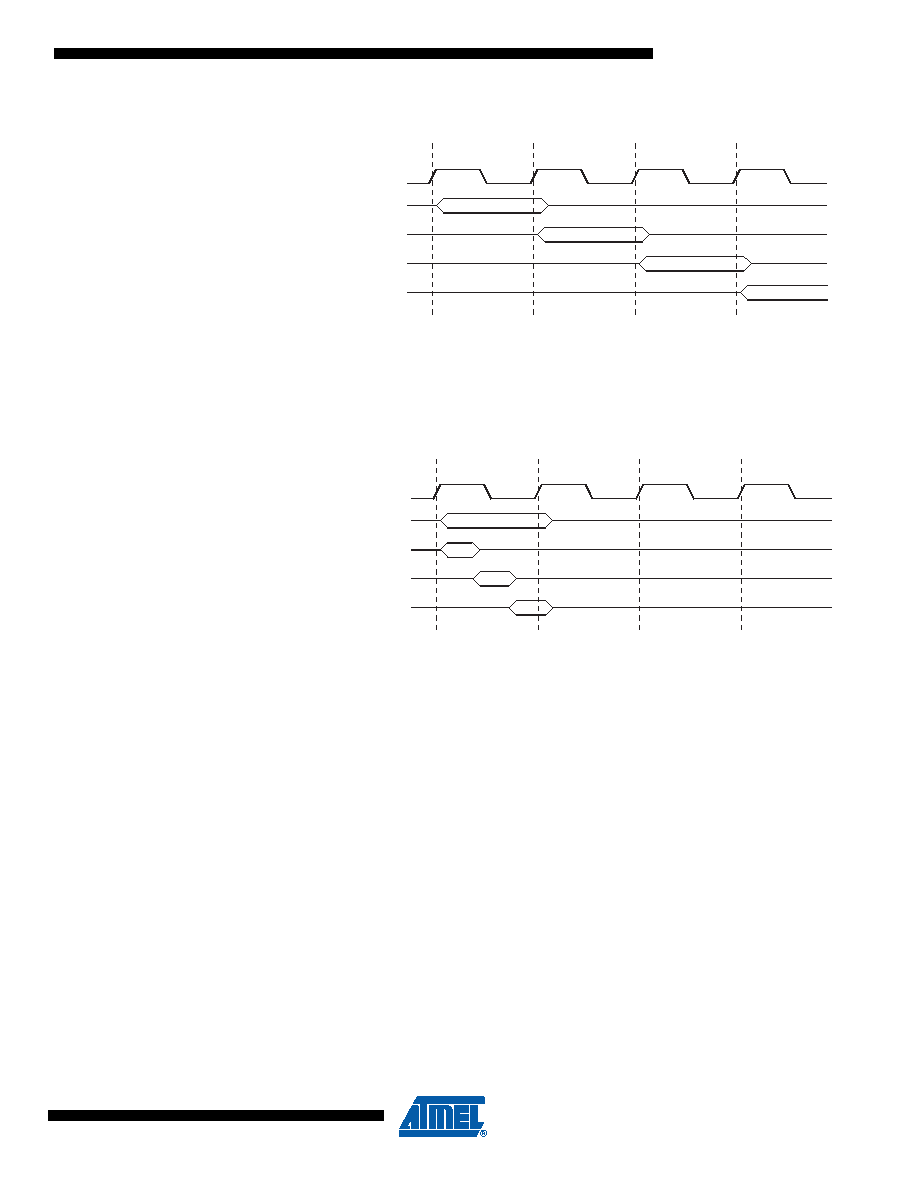
Figure 4-4.
The Parallel Instruction Fetches and Instruction Executions
Figure 4-5 shows the internal timing concept for the Register File. In a single clock cycle an ALU
operation using two register operands is executed, and the result is stored back to the destina-
tion register.
Figure 4-5.
Single Cycle ALU Operation
4.8
Reset and Interrupt Handling
The AVR provides several different interrupt sources. These interrupts and the separate Reset
Vector each have a separate program vector in the program memory space. All interrupts are
assigned individual enable bits which must be written logic one together with the Global Interrupt
Enable bit in the Status Register in order to enable the interrupt. Depending on the Program
Counter value, interrupts may be automatically disabled when Boot Lock bits BLB02 or BLB12
are programmed. This feature improves software security. See the section “Memory Program-
ming” on page 243 for details.
The lowest addresses in the program memory space are by default defined as the Reset and
Interrupt Vectors. The complete list of vectors is shown in “Interrupts” on page 63. The list also
determines the priority levels of the different interrupts. The lower the address the higher is the
priority level. RESET has the highest priority, and next is INT0 – the External Interrupt Request
0. The Interrupt Vectors can be moved to the start of the Boot Flash section by setting the IVSEL
bit in the MCU Control Register (MCUCR). Refer to “Interrupts” on page 63 for more information.
The Reset Vector can also be moved to the start of the Boot Flash section by programming the
BOOTRST Fuse, see “Memory Programming” on page 243.
When an interrupt occurs, the Global Interrupt Enable I-bit is cleared and all interrupts are dis-
abled. The user software can write logic one to the I-bit to enable nested interrupts. All enabled
interrupts can then interrupt the current interrupt routine. The I-bit is automatically set when a
Return from Interrupt instruction – RETI – is executed.
clk
1st Instruction Fetch
1st Instruction Execute
2nd Instruction Fetch
2nd Instruction Execute
3rd Instruction Fetch
3rd Instruction Execute
4th Instruction Fetch
T1
T2
T3
T4
CPU
Total Execution Time
Register Operands Fetch
ALU Operation Execute
Result Write Back
T1
T2
T3
T4
clk
CPU
相关PDF资料 |
PDF描述 |
|---|---|
| IDT71342SA35PF | IC SRAM 32KBIT 35NS 64TQFP |
| 1-84984-4 | CONN FFC 14POS 1.00MM VERT PCB |
| MPC866TCVR100A | IC MPU POWERQUICC 100MHZ 357PBGA |
| 4-1734839-6 | CONN FPC 46POS .5MM RT ANG SMD |
| MPC8275VRMIBA | IC MPU POWERQUICC II 516-PBGA |
相关代理商/技术参数 |
参数描述 |
|---|---|
| ATF16V8B-15SU SL383 | 制造商:Atmel Corporation 功能描述:SPLD ATF16V8B Family 250 Gates 8 Macro Cells 62MHz 5V 20-Pin SOIC 制造商:Atmel Corporation 功能描述:SPLD ATF16V8B Family 250 Gates 8 Macro Cells 62MHz CMOS Technology 5V 20-Pin SOIC 制造商:Atmel 功能描述:SPLD ATF16V8B Family 250 Gates 8 Macro Cells 62MHz CMOS Technology 5V 20-Pin SOIC 制造商:Atmel 功能描述:SPLD ATF16V8B Family 250 Gates 8 Macro Cells 62MHz 5V 20-Pin SOIC |
| ATF16V8B-15XC | 制造商:ATMEL 制造商全称:ATMEL Corporation 功能描述:Highperformance EE PLD |
| ATF16V8B-15XI | 制造商:未知厂家 制造商全称:未知厂家 功能描述:Electrically-Erasable PLD |
| ATF16V8B-15XU | 制造商:ATMEL 制造商全称:ATMEL Corporation 功能描述:Highperformance EE PLD |
| ATF16V8B-25GC | 制造商:未知厂家 制造商全称:未知厂家 功能描述:Electrically-Erasable PLD |
发布紧急采购,3分钟左右您将得到回复。