参数资料
| 型号: | BA3121F-E2 |
| 厂商: | Rohm Semiconductor |
| 文件页数: | 2/7页 |
| 文件大小: | 0K |
| 描述: | IC AMP AUDIO STER AB 8SOP |
| 特色产品: | Audio IC - Ground Isolation Amplifier |
| 标准包装: | 1 |
| 类型: | AB 类 |
| 输出类型: | 2 通道(立体声) |
| 电源电压: | 4 V ~ 18 V |
| 安装类型: | 表面贴装 |
| 供应商设备封装: | 8-SOP |
| 封装/外壳: | 8-SOIC(0.173",4.40mm 宽) |
| 包装: | 标准包装 |
| 产品目录页面: | 1369 (CN2011-ZH PDF) |
| 其它名称: | BA3121F-E2DKR |
2
PS8862L
05/01/09
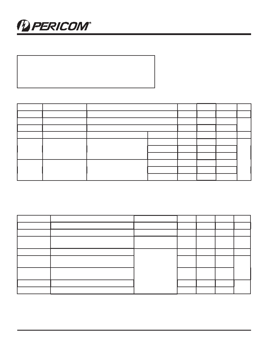
PI6C10807
1.8V/2.5V, 250MHz, 1:10 Networking Clock Buffer
Storage Temperature...........................................................–65°C to +150°C
VDD Voltage ..........................................................................–0.5V to +3.6V
Output Voltage (max. 3.6V) .......................................... –0.5V to VDD+0.5V
Input Voltage (max 3.6V).............................................. –0.5V to VDD+0.5V
2.5V Absolute Maximum Ratings (Above which the useful life may be impaired. For user guidelines only, not tested.)
Note: Stresses greater than those listed under MAXI-
MUM RATINGS may cause permanent damage to the
device. This is a stress rating only and functional operation
of the device at these or any other conditions above those
indicated in the operational sections of this specication is
not implied. Exposure to absolute maximum rating condi-
tions for extended periods may affect reliability.
2.5V AC Characteristics (Over Operating Range: VDD = 2.5V ± 0.2V, TA = -40° to 85°C)
Parameters
Description
Test Conditions1
Min.
Typ
Max.
Units
FIN
Input Frequency
0
250
MHz
tR/tF
CLKn Rise/Fall Time
20% to 80%
1.0
ns
tSK(P)3. 5
Pulse Skew between opposite transitions
(tPHL-tPLH) of the same output
Vin > VDD
CL = 5pF, 125 MHz
100
200
ps
tPLH, tPHL2, 5
Propagation Delay BUF_IN to CLKn
CL = 5pF, 125 MHz
1.0
1.5
2.0
ns
tSK(O)3, 5
Output to Output Skew between any two
outputs of the same device @ same transition
60
ps
tSK(T)3, 5
Part to Part Skew between two identical out-
puts of different parts on the same board4
300
tdc_in 5
Duty Cycle In @ Ins edge rate
45
55
%
tdc_out 5
Duty Cycle Out
40
57.5
Notes:
1. See test circuit and waveforms.
2. Minimum limits are guaranteed but not tested on Propagation Delays.
3. Skew measured at worst case temperature (max. temp).
4.
Identical conditions: loading, transitions, supply voltage, temperature, package type and speed grade.
5.
Outputs are measured at VDD/2
2.5V DC Characteristics (Over Operating Range: VDD = 2.5V ± 0.2V, TA = -40° to 85°C)
Parameters Description
Test Conditions1
Min.
Typ.2
Max.
Units
VDD
Supply Voltage
2.3
2.5
2.7
VIH
Input HIGH Voltage
Logic HIGH level
1.7
3.6
V
VIL
Input LOW Voltage
Logic LOW level
-0.3
0.7
II
Input Current
VDD = Max, Vin = VDD or GND
15
μA
VOH
Output High Voltage
VDD = Min., VIN = VIH or VIL
IOH = -1mA
2.0
V
IOH = -2mA
1.7
IOH = -8mA
1.7
VOL
Output LOW Voltage
VDD = Min., VIN - VIH or VIL
IOL = 1mA
0.1
IOL = 2mA
0.2
IOL = 8mA
0.2
Notes:
1.
For Max. or Min. conditions, use appropriate operating range values.
2. Typical values are at VDD = 2.5V, +25°C ambient and maximum loading.
09-0084
相关PDF资料 |
PDF描述 |
|---|---|
| BA5406 | IC AMP AUDIO 5W STER AB 12SIP |
| BD3460FS-E2 | IC SOUND PROCESSOR 6CH 24-SSOP |
| BD3812F-E2 | IC SOUND PROCESSOR 2CH 14SOP |
| BD3813KS-E2 | IC SOUND PROCESSOR 6CH 56SQFP |
| BD3814FV-E2 | IC SOUND PROCESSOR 6CH 40SSOP |
相关代理商/技术参数 |
参数描述 |
|---|---|
| BA3121F-E2-CUT TAPE | 制造商:ROHM 功能描述:Dual Channel 18 V 450 mW 1.5 dB SMT Ground Isolation Audio Amplifier - SOP-8 |
| BA3121N | 功能描述:音频放大器 IC AMP ISOLATION 2CH 18V RoHS:否 制造商:STMicroelectronics 产品:General Purpose Audio Amplifiers 输出类型:Digital 输出功率: THD + 噪声: 工作电源电压:3.3 V 电源电流: 最大功率耗散: 最大工作温度: 安装风格:SMD/SMT 封装 / 箱体:TQFP-64 封装:Reel |
| BA3123F | 制造商:ROHM 制造商全称:Rohm 功能描述:Ground Isolation Amplifier |
| BA3123F-E2 | 制造商:ROHM Semiconductor 功能描述:GROUND ISOLATION AMPLIFIER 8-PIN SOP T/R - Tape and Reel 制造商:ROHM Semiconductor 功能描述:IC AMP GROUND ISOLATION 8-SOP 制造商:ROHM Semiconductor 功能描述:GROUND ISO AMP 8PIN |
| BA3124 | 制造商:未知厂家 制造商全称:未知厂家 功能描述: |
发布紧急采购,3分钟左右您将得到回复。