- 您现在的位置:买卖IC网 > PDF目录16693 > BD6222FP-EVAL-N (Rohm Semiconductor)BOARD EVAL FOR BD6222FP PDF资料下载
参数资料
| 型号: | BD6222FP-EVAL-N |
| 厂商: | Rohm Semiconductor |
| 文件页数: | 13/22页 |
| 文件大小: | 0K |
| 描述: | BOARD EVAL FOR BD6222FP |
| 特色产品: | H-Bridge Driver IC |
| 标准包装: | 1 |
| 主要目的: | 电源管理,电机控制 |
| 嵌入式: | 否 |
| 已用 IC / 零件: | BD6222 |
| 主要属性: | 1 个半桥驱动器 |
| 已供物品: | 板 |
| 相关产品: | BD6222HFPDKR-ND - IC H-BRIDGE DVR 18V 1CH 2A HRP7 BD6222HFPCT-ND - IC H-BRIDGE DVR 18V 1CH 2A HRP7 BD6222HFPTR-ND - IC H-BRIDGE DVR 18V 1CH 2A HRP7 BD6222FP-E2DKR-ND - IC H-BRIDGE DRIVER 1CH 2A HSOP25 BD6222FP-E2CT-ND - IC H-BRIDGE DRIVER 1CH 2A HSOP25 BD6222FP-E2TR-ND - IC H-BRIDGE DRIVER 1CH 2A HSOP25 |
| 其它名称: | EVAL-N.BD6222FP EVAL-N.BD6222FP-ND |
�� �
�
�BD622xxx� Series�
�Datasheet�
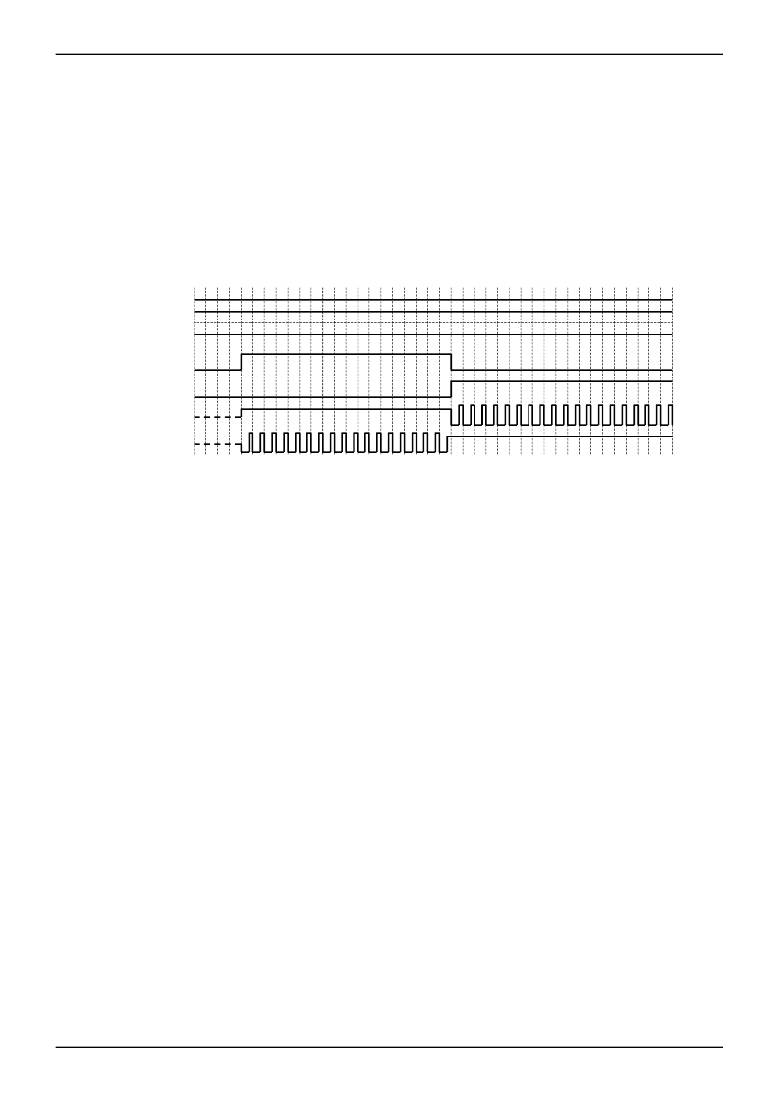
�i)� j)� VREF� control� mode�
�The� built-in� VREF� duty� cycle� conversion� circuit� provides� a� duty� cycle� corresponding� to� the� voltage� of� the� VREF� pin�
�and� the� VCC� voltage.� The� function� offers� the� same� level� of� control� as� the� high� voltage� output� setting� function� in�
�previous� models.� The� duty� cycle� is� calculated� by� the� following� equation.�
�DUTY� ≈� VREF� [V]� /� VCC� [V]�
�For� example,� if� VCC� voltage� is� 12V� and� VREF� pin� voltage� is� 9V,� the� duty� cycle� is� about� 75� percent.� However,� please�
�note� that� the� duty� cycle� might� be� limited� by� the� range� of� the� VREF� pin� voltage� (Refer� to� the� operating� conditions,�
�shown� on� page� 2).� The� PWM� carrier� frequency� in� this� mode� is� 25kHz� (nominal),� and� the� switching� operation� is� the�
�same� as� the� PWM� control� modes.� When� operating� in� this� mode,� do� not� input� a� PWM� signal� to� the� FIN� and� RIN� pins.�
�In� addition,� establish� a� current� path� for� the� recovery� current� from� the� motor,� by� connecting� a� bypass� capacitor� (10μF�
�or� more� is� recommended)� between� VCC� and� ground.�
�VCC�
�VREF�
�0�
�FIN�
�RIN�
�OUT1�
�OUT2�
�Fig.38� VREF� control� operation� (timing� chart)�
�2)�
�3)�
�Cross-conduction� protection� circuit�
�In� the� full� bridge� output� stage,� when� the� upper� and� lower� transistors� are� turned� on� at� the� same� time� during� high� to�
�low� or� low� to� high� transition,� an� inrush� current� flows� from� the� power� supply� to� ground,� resulting� to� a� loss.� This� circuit�
�eliminates� the� inrush� current� by� providing� a� dead� time� (about� 400ns,� nominal)� during� the� transition.�
�Output� protection� circuits�
�a)� Under� voltage� lock� out� (UVLO)� circuit�
�To� ensure� the� lowest� power� supply� voltage� necessary� to� operate� the� controller,� and� to� prevent� under� voltage�
�malfunctions,� a� UVLO� circuit� has� been� built� into� this� driver.� When� the� power� supply� voltage� falls� to� 5.0V� (nominal)� or�
�below,� the� controller� forces� all� driver� outputs� to� high� impedance.� When� the� voltage� rises� to� 5.5V� (nominal)� or� above,�
�the� UVLO� circuit� ends� the� lockout� operation� and� returns� the� chip� to� normal� operation.�
�b)� Over� voltage� protection� (OVP)� circuit�
�When� the� power� supply� voltage� exceeds� 30V� (nominal),� the� controller� forces� all� driver� outputs� to� high� impedance.�
�The� OVP� circuit� is� released� and� its� operation� ends� when� the� voltage� drops� back� to� 25V� (nominal)� or� below.� This�
�protection� circuit� does� not� work� in� the� stand-by� mode.� Also,� note� that� this� circuit� is� supplementary,� and� thus� if� it� is�
�asserted,� the� absolute� maximum� rating� will� have� been� exceeded.� Therefore,� do� not� continue� to� use� the� IC� after� this�
�circuit� is� activated,� and� do� not� operate� the� IC� in� an� environment� where� activation� of� the� circuit� is� assumed.�
�www.rohm.com�
�?� 2012� ROHM� Co.,� Ltd.� All� rights� reserved.�
�TSZ22111� ?� 15� ?� 001�
�13/19�
�TSZ02201-0P2P0B300080-1-2�
�25.Dec.2012� Rev.002�
�相关PDF资料 |
PDF描述 |
|---|---|
| A3DDB-1036M | IDC CABLE- AKR10B/AE10M/AKR10B |
| RBM06DTAS-S189 | CONN EDGECARD 12POS R/A .156 SLD |
| GCC10DRTF-S13 | CONN EDGECARD 20POS .100 EXTEND |
| EBM28DCTN-S288 | CONN EDGECARD 56POS .156 EXTEND |
| H2MXS-2636M | DIP CABLE - HDM26S/AE26M/X |
相关代理商/技术参数 |
参数描述 |
|---|---|
| BD6222HFP | 制造商:ROHM 制造商全称:Rohm 功能描述:H-bridge driver for DC brush motor |
| BD6222HFP-TR | 功能描述:马达/运动/点火控制器和驱动器 H-BRIDGE 18V max 1 Chan 2.0A 1.0ohm RoHS:否 制造商:STMicroelectronics 产品:Stepper Motor Controllers / Drivers 类型:2 Phase Stepper Motor Driver 工作电源电压:8 V to 45 V 电源电流:0.5 mA 工作温度:- 25 C to + 125 C 安装风格:SMD/SMT 封装 / 箱体:HTSSOP-28 封装:Tube |
| BD6222HFP-TR-CUT TAPE | 制造商:ROHM 功能描述:Single Channel Dual Output 15 V 2 A SMT Brush Motor H-Bridge Driver - HRP-7 |
| BD6225 | 制造商:ROHM 制造商全称:Rohm 功能描述:H-bridge drivers (18V max.) |
| BD6225FP | 制造商:ROHM 制造商全称:Rohm 功能描述:18V max. H-bridge Drivers |
发布紧急采购,3分钟左右您将得到回复。