- 您现在的位置:买卖IC网 > PDF目录256292 > BU-61559D1-100S (DATA DEVICE CORP) 2 CHANNEL(S), 1M bps, MIL-STD-1553 CONTROLLER, CQIP78 PDF资料下载
参数资料
| 型号: | BU-61559D1-100S |
| 厂商: | DATA DEVICE CORP |
| 元件分类: | 微控制器/微处理器 |
| 英文描述: | 2 CHANNEL(S), 1M bps, MIL-STD-1553 CONTROLLER, CQIP78 |
| 封装: | 45.70 X 53.30 MM, 5.30 MM HEIGHT, CERAMIC, DDIP-78 |
| 文件页数: | 8/32页 |
| 文件大小: | 438K |
| 代理商: | BU-61559D1-100S |
第1页第2页第3页第4页第5页第6页第7页当前第8页第9页第10页第11页第12页第13页第14页第15页第16页第17页第18页第19页第20页第21页第22页第23页第24页第25页第26页第27页第28页第29页第30页第31页第32页
16
Data Device Corporation
www.ddc-web.com
BU-61559 Series
E-03/06-0
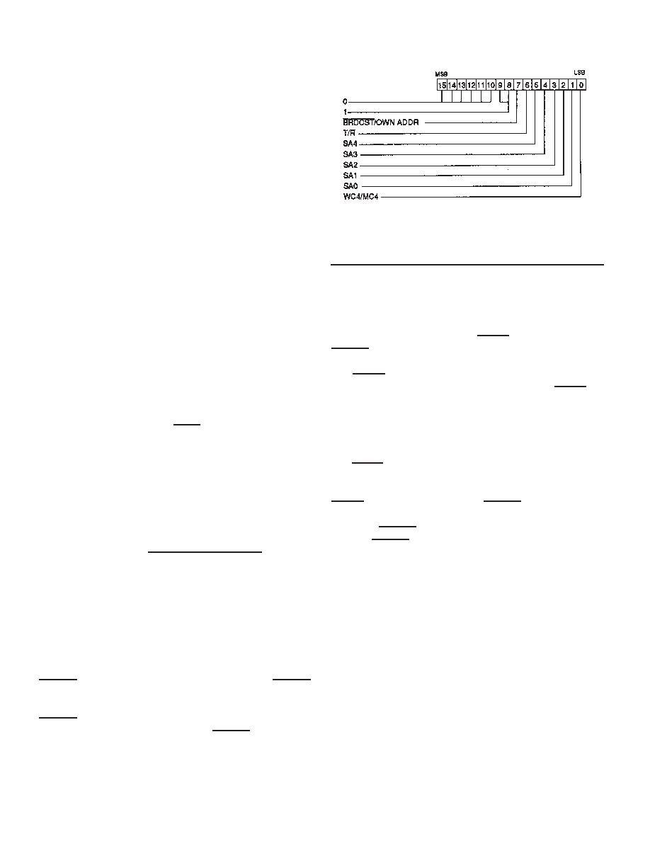
(2) For subaddresses 00001 through 11110, the “WC/MC” field
specifies the Word Count field of the respective Command
Word. For subaddresses 00000 and 11111, the “WC/MC”
field specifies the Mode Code field of the respective
Command Word.
(3) Since non-mode code broadcast transmit messages are not
defined by MIL-STD-1553B, the sixty (60) words in the illegal-
ization RAM, addresses 0342 through 037D, corresponding to
these commands do not need to be initialized. The BU-61559
will not respond to a non-mode code broadcast transmit com-
mand, but will automatically set the Message Error bit in its
internal Status Register, regardless of whether or not the cor-
responding bit in the illegalization RAM has been set. If the next
message is a Transmit Status or Transmit Last Command mode
code, the BU-61559 will respond with its Message Error bit set.
BROADCAST OPTION
In RT mode, the BU-61559 supports the use of broadcast mes-
sages as a pin-programmable option. If the input signal
BRO_ENA is connected to logic 1 (+5V), the BU-61559 will rec-
ognize RT Address 31 as the broadcast address. If BRO_ENA is
connected to logic 0 (ground), then RT Address 31 will not be
recognized as the broadcast address and may be used as a dis-
crete terminal address. MIL-STD-1553B stipulates that RT
address 31 shall not be assigned as a discrete terminal address.
BUSY BIT
If the host CPU asserts the BUSY bit low in Configuration
Register #1, the BU-61559 will respond with the BUSY bit set in
its RT Status Word. For a receive command, words will be writ-
ten to the data block in the shared RAM referenced by the
respective Lookup Table location. For a transmit command, the
AIM will respond with Status/BUSY, but no data words will be
transmitted.
DYNAMIC BUS CONTROL ACCEPTANCE
The Dynamic Bus Control Acceptance bit in the RT Status Word
will only be set if the DYNAMIC BUS ACCEPT bit in the
Configuration Register is set to logic 0 and the RT is responding
to a Dynamic Bus Control mode code. It should be noted that the
BU-61559 will not automatically switch from RT to BC mode fol-
lowing reception (and acceptance) of a Dynamic Bus Control
mode command.
SUBSYSTEM FLAG STATUS WORD BIT
The Subsystem Flag Status Word bit is controllable from the host
processor by means of bit 8 of Configuration Register #1,
SSFLAG. The Subsystem Flag Status bit will be set if SSFLAG
is programmed to logic “0”. In addition, the Subsystem Flag
Status Word bit will also be set if a logic “0” is applied to the
SSFLAG input pin. For some applications, the output of a CPU
watchdog timer may be connected to the SSFLAG input pin. This
provides a mechanism for the system bus controller to determine
that the RT's host processor has failed.
FIGURE 16. ILLEGALIZING RAM ADDRESS
DEFINITION
RTFAIL, RTFLAG SIGNALS
The BU-61559 provides a degree of flexibility for the purposes of
monitoring of the RT built-in self-test by the host processor as
well as in formulation of the RT FLAG Status Word bit. This is
accomplished by bringing out the RTFAIL output signal and the
RTFLAG input signal.
The RTFAIL output is updated following every non-broadcast
message processed by the BU-61559 in RT mode. RTFAIL will
be asserted low following either a timeout of the Transmitter
Failsafe timer (768 s) and/or a failure of the looptest. A looptest
failure indicates either a mismatch in the bit pattern and/or an
invalid word for the received version of the last transmitted word.
The RTLAG input is used to control the RT Flag bit in the BU-
61559's RT Status Word. It is sampled following the reception of
all valid non-broadcast Command Words. In most applications,
RTFAIL will be connected directly to RTFLAG. In other instances,
provisions may be implemented such that the host processor can
control the RTFLAG input to the BU-61559. This allows the CPU
to assert RTFLAG low following failure of a software-driven self-
test of the BU-61559.
MONITOR OPERATION
To initialize the BU-61559 for Monitor (MT) mode, the host
processor should program the upper two bits of Configuration
Register #1 to 0 and 1 respectively. Next, the Stack Pointer for
the active area should be loaded with the starting location of the
monitor stack in the BU-61559 shared RAM address space.
Finally, to start the monitor, a “Start” command should be issued
by means of the Start/Reset Register.
In Monitor mode, the BU-61559 continuously monitors both 1553
bus channels, storing all words to the shared RAM in the order
in which they are received. For each word received from the 1553
bus, the BU-61559 stores two 16-bit words to the shared RAM
相关PDF资料 |
PDF描述 |
|---|---|
| BU-61559D1-100W | 2 CHANNEL(S), 1M bps, MIL-STD-1553 CONTROLLER, CQIP78 |
| BU-61559D1-430W | 2 CHANNEL(S), 1M bps, MIL-STD-1553 CONTROLLER, CQIP78 |
| BU-61559D1-430 | 2 CHANNEL(S), 1M bps, MIL-STD-1553 CONTROLLER, CQIP78 |
| BU-61559D2-420Z | 2 CHANNEL(S), 1M bps, MIL-STD-1553 CONTROLLER, CQIP78 |
| BU-61559D2-430Z | 2 CHANNEL(S), 1M bps, MIL-STD-1553 CONTROLLER, CQIP78 |
相关代理商/技术参数 |
参数描述 |
|---|---|
| BU-61580 | 制造商:未知厂家 制造商全称:未知厂家 功能描述:MIL-STD-1553 Components |ACE |
| BU-61580G1-100 | 制造商:未知厂家 制造商全称:未知厂家 功能描述:MIL-STD-1553/ARINC Bus Controller/RTU |
| BU-61580G1-110 | 制造商:未知厂家 制造商全称:未知厂家 功能描述:MIL-STD-1553/ARINC Bus Controller/RTU |
| BU-61580G1-120 | 制造商:未知厂家 制造商全称:未知厂家 功能描述:MIL-STD-1553/ARINC Bus Controller/RTU |
| BU-61580G1-200 | 制造商:未知厂家 制造商全称:未知厂家 功能描述:MIL-STD-1553/ARINC Bus Controller/RTU |
发布紧急采购,3分钟左右您将得到回复。