- 您现在的位置:买卖IC网 > PDF目录256079 > BU-61559D1-110Z (DATA DEVICE CORP) 2 CHANNEL(S), 1M bps, MIL-STD-1553 CONTROLLER, CQIP78 PDF资料下载
参数资料
| 型号: | BU-61559D1-110Z |
| 厂商: | DATA DEVICE CORP |
| 元件分类: | 微控制器/微处理器 |
| 英文描述: | 2 CHANNEL(S), 1M bps, MIL-STD-1553 CONTROLLER, CQIP78 |
| 封装: | 45.70 X 53.30 MM, 5.30 MM HEIGHT, CERAMIC, DDIP-78 |
| 文件页数: | 31/32页 |
| 文件大小: | 438K |
| 代理商: | BU-61559D1-110Z |
第1页第2页第3页第4页第5页第6页第7页第8页第9页第10页第11页第12页第13页第14页第15页第16页第17页第18页第19页第20页第21页第22页第23页第24页第25页第26页第27页第28页第29页第30页当前第31页第32页
8
Data Device Corporation
www.ddc-web.com
BU-61559 Series
E-03/06-0
TIME TAG
The second word of the Message Block Descriptor is the 16-bit
Time Tag. The Time Tag value is written from the Time Tag
Register during the BC SOM sequence. The resolution of the
Time Tag Register is programmable from among 2, 4, 8, 16, 32,
64, or “External” (variable) s/LSB. After the host processor has
determined the message status by reading the message block
descriptor, it may then read the results of the message from the
respective message block. That is, it should read the received
Loopback word, followed by the RT Status Word(s), and possibly
Data words received from the responding RT.
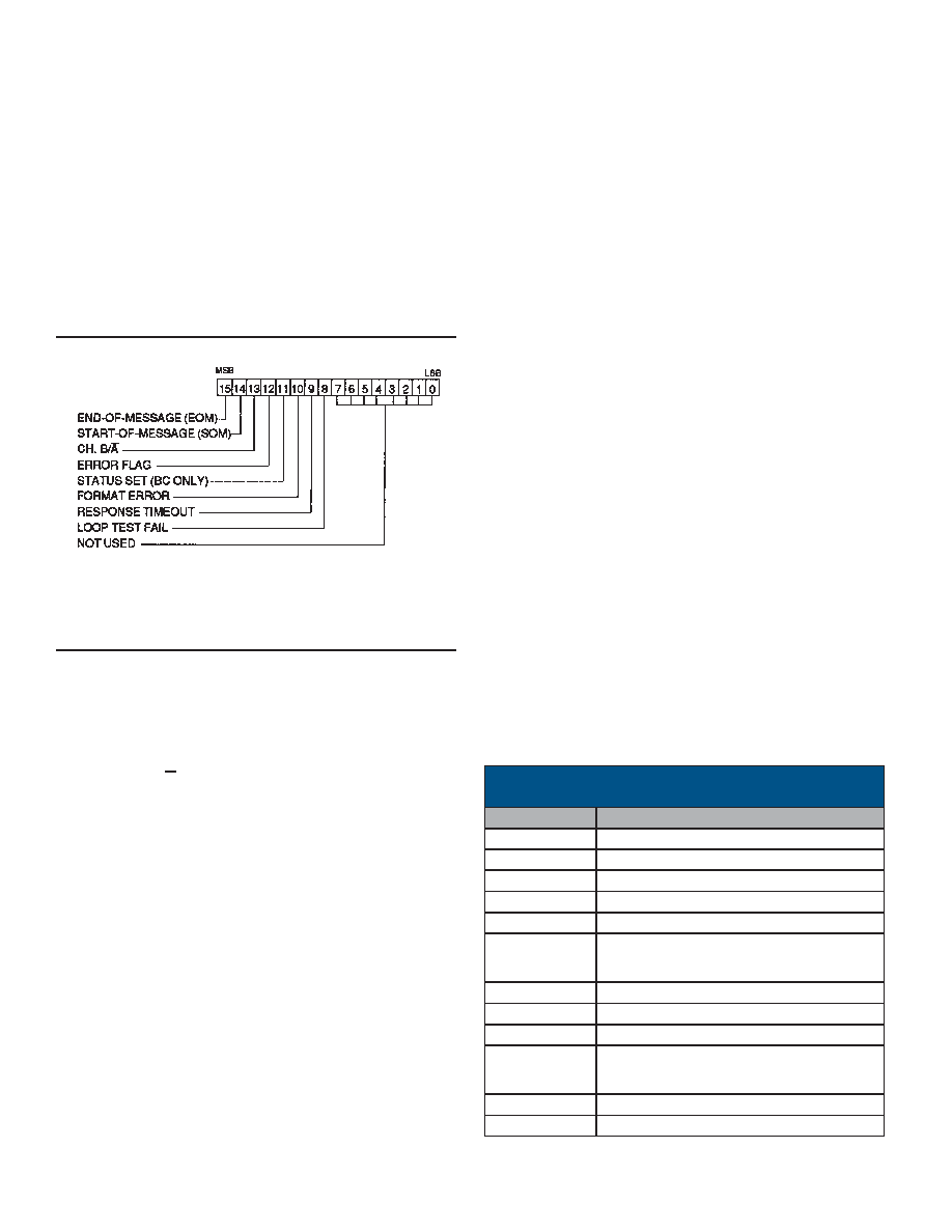
FIGURE 10. BLOCK STATUS WORD
BC OPERATION
The BC protocol of the BU-61559 implements all MIL-STD-
1553B message formats. Message format is programmable on a
message-by-message basis by means of individual BC Control
Words and the T/R bit of the Command Word to be transmitted.
In addition to message format, the BC Control Word allows bus
channel, self-test, and Status Word masking to be specified on
an individual message basis. The BC performs all error checking
required by 1553B. This includes validation of sync type and
encoding, Manchester II encoding, parity, bit count, word count,
and Status Word RT Address field. RT response time is verified
to be less than the BU-61559's response timeout value of 17.5 to
22.5 s.
BC MEMORY ORGANIZATION
TABLE 2 illustrates a typical memory map for BC mode. It is
important to note that the only fixed locations for the BU-61559
in BC mode are for the two Stack Pointers (address locations
0100 (hex) and 0104) and for the two Message Count locations
(0101 and 0105). The user is free to locate the Stack and BC
Message Blocks anywhere else within the 64K (8K internal)
shared RAM address space.
For simplicity of illustration, 64 words are allocated for each BC
message block in the typical BC memory map of TABLE 2. Note,
however, that the actual maximum size of a BC message block
is 38 words, for an RT-to-RT transfer of 32 Data Words (Control
+ 2 Commands + Loopback + 2 Status Words + 32 Data Words).
Therefore, it is possible to pack more messages into the shared
RAM address space, particularly if the 256-word boundaries are
disabled.
ACTIVE AREAS DOUBLE BUFFERING
The Active Area facility provides a global mechanism for dividing
the shared RAM into “active” and “non-active” areas. At any point
in time, only the various data structures within the “active” area
are accessed by the internal 1553 memory management logic. It
should be noted, however, that at any point in time, both the
active and non-active areas are accessible by the host proces-
sor.
An overview of the BU-61559's memory management scheme for
BC mode is illustrated in FIGURE 11. The BC may be pro-
grammed to transmit multi-message frames of up to 64 unique
messages and up to 256 total messages per frame. The number
of messages to be processed is programmable by means of a
fixed Message Count location in the shared RAM. In addition, the
host processor must initialize a second fixed location as the Stack
Pointer. This RAM location contains a pointer that references the
four-word message block descriptor (in the Stack area of shared
RAM) for each message to be processed. Each message resides
in a designated message block area of the shared RAM. The
starting location for each message block is specified by a pointer
that is stored in the fourth location of the block descriptor for the
respective message. This pointer must be loaded by the host
processor before the message is processed. The first word of
each BC message block is the BC Control Word.
ADDRESS (HEX)
0000-00FF
Stack A
0100
Stack Pointer A (fixed location)
0101
Message Count A (fixed location)
0104
Stack Pointer B (fixed location)
0105
Message Count B (fixed location)
0140-017F
Message Block 0
0180-01BF
Message Block 1
01C0-01FF
Message Block 2
1EC0-1EFF
Message Block 118
1F00-1FFF
Stack B
TABLE 2. TYPICAL BC MEMORY MAP
(SHOWN FOR 8K RAM)
DESCRIPTION
Note: Bits 7 through 0 will read as FF (hex) after the Block Status Word has been
written to shared RAM during a Start-of-Message (SOM) or End-of-
Message (EOM) sequence.
相关PDF资料 |
PDF描述 |
|---|---|
| BU-61559D1-130 | 2 CHANNEL(S), 1M bps, MIL-STD-1553 CONTROLLER, CQIP78 |
| BU-61559D1-140Y | 2 CHANNEL(S), 1M bps, MIL-STD-1553 CONTROLLER, CQIP78 |
| BU-61559D1-410S | 2 CHANNEL(S), 1M bps, MIL-STD-1553 CONTROLLER, CQIP78 |
| BU-61559D1-410Y | 2 CHANNEL(S), 1M bps, MIL-STD-1553 CONTROLLER, CQIP78 |
| BU-61559D1-450L | 2 CHANNEL(S), 1M bps, MIL-STD-1553 CONTROLLER, CQIP78 |
相关代理商/技术参数 |
参数描述 |
|---|---|
| BU-61580 | 制造商:未知厂家 制造商全称:未知厂家 功能描述:MIL-STD-1553 Components |ACE |
| BU-61580G1-100 | 制造商:未知厂家 制造商全称:未知厂家 功能描述:MIL-STD-1553/ARINC Bus Controller/RTU |
| BU-61580G1-110 | 制造商:未知厂家 制造商全称:未知厂家 功能描述:MIL-STD-1553/ARINC Bus Controller/RTU |
| BU-61580G1-120 | 制造商:未知厂家 制造商全称:未知厂家 功能描述:MIL-STD-1553/ARINC Bus Controller/RTU |
| BU-61580G1-200 | 制造商:未知厂家 制造商全称:未知厂家 功能描述:MIL-STD-1553/ARINC Bus Controller/RTU |
发布紧急采购,3分钟左右您将得到回复。