- 您现在的位置:买卖IC网 > PDF目录256079 > BU-61559D1-110Z (DATA DEVICE CORP) 2 CHANNEL(S), 1M bps, MIL-STD-1553 CONTROLLER, CQIP78 PDF资料下载
参数资料
| 型号: | BU-61559D1-110Z |
| 厂商: | DATA DEVICE CORP |
| 元件分类: | 微控制器/微处理器 |
| 英文描述: | 2 CHANNEL(S), 1M bps, MIL-STD-1553 CONTROLLER, CQIP78 |
| 封装: | 45.70 X 53.30 MM, 5.30 MM HEIGHT, CERAMIC, DDIP-78 |
| 文件页数: | 5/32页 |
| 文件大小: | 438K |
| 代理商: | BU-61559D1-110Z |
第1页第2页第3页第4页当前第5页第6页第7页第8页第9页第10页第11页第12页第13页第14页第15页第16页第17页第18页第19页第20页第21页第22页第23页第24页第25页第26页第27页第28页第29页第30页第31页第32页
13
Data Device Corporation
www.ddc-web.com
BU-61559 Series
E-03/06-0
address. The other of these two bits will result in an interrupt at
the end of a message if the message resulted in the Lookup
Table pointer for the respective Tx/Rx/Bcst-subaddress crossing
the lower boundary of the circular buffer, rolling over to the top of
the buffer.
SINGLE MESSAGE MODE
If bit 1 of Configuration Register #2 is logic 0, the BU-61559's
memory management scheme assumes its default or non-
enhanced mode. In the non-enhanced RT operation, the single
message memory management mode is used for all receive,
transmit, or broadcast subaddresses. In addition, under the
enhanced RT memory management scheme, the single mes-
sage mode may still be used for individual receive, transmit,
and/or broadcast subaddresses. This is the case if the three
applicable “memory management” bits in the respective
Subaddress Control Word are set to logic 0.
The operation of the single message RT memory management
mode is illustrated in FIGURE 14. In the single message mode,
the Lookup Table must be loaded by the host processor. At the
start of each message, the Lookup Table entry is stored in the
third position of the respective message block descriptor in the
Stack area of RAM. Received Data Words are written to or trans-
mitted Data Words are read from the Data Block referenced by
the respective Lookup Table Pointer. In the single message
mode, the current Lookup Table pointer is not written to by the
BU-61559 memory management logic at the end of a message.
Therefore, if a subsequent message is processed for the same
subaddress, the same Data Block will be overwritten or over-
read.
CIRCULAR BUFFER MODE
In the enhanced RT memory management mode, individual
transmit, receive, and broadcast subaddresses may be pro-
grammed for either the single message or circular buffer modes.
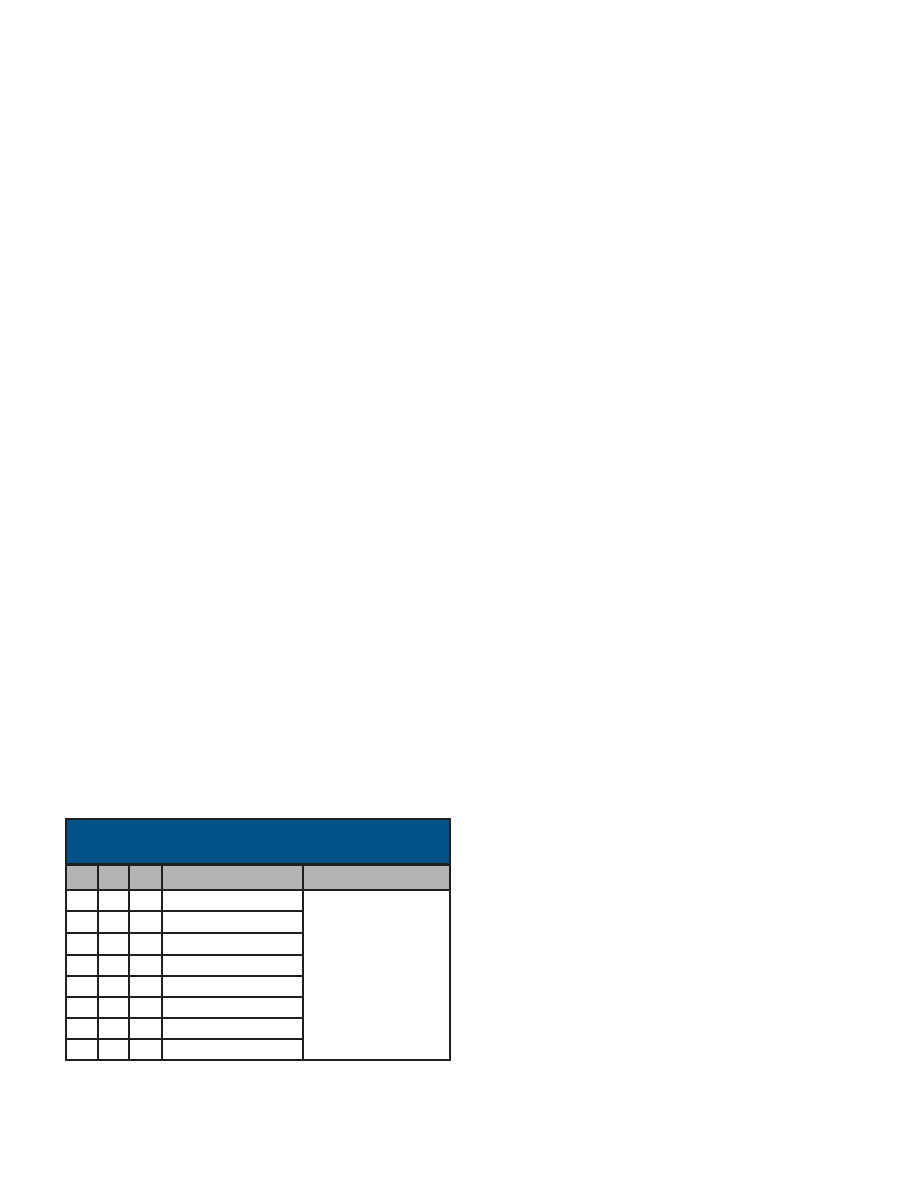
Circular buffer
of specified size.
8192-Word
1
4096-Word
0
1
1024-Word
0
1
512-Word
1
0
256-Word
0
1
0
128-Word
1
0
Single Buffer
0
MM0
DESCRIPTION
COMMENT
MM1
MM2
TABLE 5. SUBADDRESS CONTROL WORD -
MEMORY MANAGEMENT OPTIONS
2048-Word
1
0
1
The operation of the circular buffer RT memory management
mode is illustrated in FIGURE 15. As in the non-enhanced mode,
the individual Lookup Table entries are initially loaded by the host
processor. At the start of each message, the Lookup Table entry
is stored in the third position of the respective message block
descriptor in the Stack area of RAM. Receive or Transmit Data
Words are transferred to (from) the circular buffer, starting at the
location referenced by the Lookup Table pointer.
Under any of the following conditions, the location after the last
address location accessed for the message will be stored into
the respective Lookup Table pointer location following the end of
a message: (1) If bit 11 of Configuration Register # 2 (OVER-
WRITE INVALID DATA) is logic 0, (2) following a transmit mes-
sage, or (3) following a valid receive or broadcast message, if bit
11 of Configuration Register #2 is logic 1. In this way, data for the
next message for the respective Tx/Rx/Bcst-subaddress will be
accessed to/from the next lower contiguous block of address
locations in the circular buffer.
If the OVERWRITE INVALID DATA bit (bit 11) of Configuration
Register #2 is logic “1”, the location after the last word accessed
for the message is stored into the respective Lookup Table loca-
tion only following a valid received (or transmitted) mes-
sage. Assuming that the value of the Lookup Table pointer is
updated, data for the next message for the respective
Tx/Rx/Bcst subaddress will be accessed to/from the next lower
contiguous block of locations in the circular buffer. If the OVER-
WRITE INVALID DATA bit is set, the Lookup Table pointer will
not be updated at the end of the message if there was an error
in the message. This allows failed messages in a bulk data trans-
fer to be retried without disturbing the circular buffer data struc-
ture, and without intervention by the RT's host processor.
When the pointer reaches the lower boundary of the circular
buffer (located at 128-, 256-, . . . 8192-word boundaries in the
shared RAM address space), the pointer moves to the top
boundary of the circular buffer, as shown in FIGURE 15.
It should be noted that the pointer to the start of the RT message
block is stored in the third location of the message block descrip-
tor (in the stack) for the single message mode as well as for the
circular buffer mode.
RT STACK AND INTERRUPTS
In RT mode, the Stack area of RAM contains a real time chronol-
ogy of all messages processed by the BU-61559. Similar to BC
mode, there is a four-word block descriptor in the Stack for each
message processed. The four entries to each block descriptor are
the Block Status Word, Time Tag Word, the pointer to the start of
the data block, and the 16-bit received Command Word. Prior to
the processing of messages, the host processor should initialize
the Stack Pointer. In some applications, it may also prove helpful
to “zero out” the Stack area prior to receiving messages.
相关PDF资料 |
PDF描述 |
|---|---|
| BU-61559D1-130 | 2 CHANNEL(S), 1M bps, MIL-STD-1553 CONTROLLER, CQIP78 |
| BU-61559D1-140Y | 2 CHANNEL(S), 1M bps, MIL-STD-1553 CONTROLLER, CQIP78 |
| BU-61559D1-410S | 2 CHANNEL(S), 1M bps, MIL-STD-1553 CONTROLLER, CQIP78 |
| BU-61559D1-410Y | 2 CHANNEL(S), 1M bps, MIL-STD-1553 CONTROLLER, CQIP78 |
| BU-61559D1-450L | 2 CHANNEL(S), 1M bps, MIL-STD-1553 CONTROLLER, CQIP78 |
相关代理商/技术参数 |
参数描述 |
|---|---|
| BU-61580 | 制造商:未知厂家 制造商全称:未知厂家 功能描述:MIL-STD-1553 Components |ACE |
| BU-61580G1-100 | 制造商:未知厂家 制造商全称:未知厂家 功能描述:MIL-STD-1553/ARINC Bus Controller/RTU |
| BU-61580G1-110 | 制造商:未知厂家 制造商全称:未知厂家 功能描述:MIL-STD-1553/ARINC Bus Controller/RTU |
| BU-61580G1-120 | 制造商:未知厂家 制造商全称:未知厂家 功能描述:MIL-STD-1553/ARINC Bus Controller/RTU |
| BU-61580G1-200 | 制造商:未知厂家 制造商全称:未知厂家 功能描述:MIL-STD-1553/ARINC Bus Controller/RTU |
发布紧急采购,3分钟左右您将得到回复。