- 您现在的位置:买卖IC网 > PDF目录166545 > BU-61580S3-120W (DATA DEVICE CORP) 2 CHANNEL(S), 1M bps, MIL-STD-1553 CONTROLLER, CQIP70 PDF资料下载
参数资料
| 型号: | BU-61580S3-120W |
| 厂商: | DATA DEVICE CORP |
| 元件分类: | 微控制器/微处理器 |
| 英文描述: | 2 CHANNEL(S), 1M bps, MIL-STD-1553 CONTROLLER, CQIP70 |
| 封装: | 48.30 X 25.40 MM, 4.19 MM HEIGHT, DIP-70 |
| 文件页数: | 41/44页 |
| 文件大小: | 563K |
| 代理商: | BU-61580S3-120W |
第1页第2页第3页第4页第5页第6页第7页第8页第9页第10页第11页第12页第13页第14页第15页第16页第17页第18页第19页第20页第21页第22页第23页第24页第25页第26页第27页第28页第29页第30页第31页第32页第33页第34页第35页第36页第37页第38页第39页第40页当前第41页第42页第43页第44页
6
Data Device Corporation
www.ddc-web.com
BU-65170/61580/61585
H1 web-09/02-0
Time Tag Register maintains the value of a real-time clock. The resolu-
tion of this register is programmable from among 2, 4, 8, 16, 32, and 64
s/LSB.The TAG_CLK input signal also may cause an external oscillator
to clock the Time Tag Register. Start-of-Message (SOM) and End-of-
Message (EOM) sequences in BC, RT, and Message Monitor modes
cause a write of the current value of the Time Tag Register to the stack
area of RAM.
Interrupt Status Register mirrors the Interrupt Mask Register and con-
tains a Master Interrupt bit. It allows the host processor to determine the
cause of an interrupt request by means of a single READ operation.
Configuration Registers #3, #4, and #5 are used to enable many of the
BU-61580's advanced features. These include all the enhanced mode
features; that is, all the functionality beyond that of the previous generation
product, the BUS-61559 Advanced Integrated Mux Hybrid with Enhanced
RT Features (AIM-HY'er).For all three modes, use of the Enhanced Mode
enables the various read-only bits in Configuration Register #1. For BC
mode, the enhanced mode features include the expanded BC Control
Word and BC Block Status Word, additional Stop-On-Error and Stop-On-
Status Set functions, frame auto-repeat, programmable intermessage
gap times, automatic retries, expanded Status Word Masking, and the
capability to generate interrupts following the completion of any selected
message. For RT mode, the enhanced mode features include the
expanded RT Block Status Word, the combined RT/Selective Message
Monitor mode, internal wrapping of the RTFAIL output signal (from the J
chip) to the RTFLAG RT Status Word bit, the double buffering scheme for
individual receive (broadcast) subaddresses, and the alternate (fully soft-
ware programmable) RT Status Word. For MT mode, use of the
enhanced mode enables use of the Selective Message Monitor, the com-
bined RT/Selective Monitor modes, and the monitor triggering capability.
Data Stack Address Register is used to point to the current address
location in shared RAM used for storing message words (second
Command Words, Data Words, RT Status Words) in the Selective Word
Monitor mode.
FrameTime Remaining Register provides a read only indication of the
time remaining in the current BC frame. The resolution of this register is
100 s/LSB.
Message Time Remaining Register provides a read only indication of
the time remaining before the start of the next message in a BC frame.
The resolution of this register is 1
s/LSB.
BC Frame/RT Last Command/MT Trigger Word Register: In BC
mode, it programs the BC frame time, for use in the frame auto-repeat
mode. The resolution of this register is 100
s/LSB, with a range of 6.55
seconds; in RT mode, this register stores the current (or most previous)
1553 Command Word processed by the ACE RT; in the Word Monitor
mode, this register specifies a 16-bit Trigger (Command) Word. The
Trigger Word may be used to start or stop the monitor, or to generate inter-
rupts.
Status Word Register and BIT Word Registers provide read-only indi-
cations of the BU-65170/61580's RT Status and BIT Words.
Test Mode Registers 0-7: These registers may be used to facilitate pro-
duction or maintenance testing of the BU-65170/61580 and systems
incorporating the BU-65170/61580.
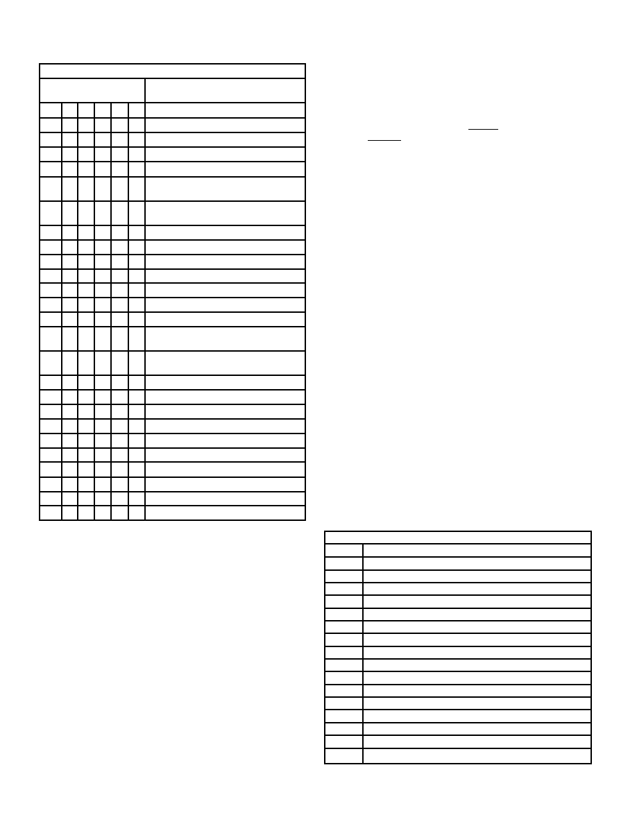
TABLE 2. ADDRESS MAPPING
ADDRESS LINES
REGISTER
DESCRIPTION/ACCESSIBILITY
HEX A4 A3 A2 A1 A0
00
0
Interrupt Mask Register (RD/WR)
01
0
1
Configuration Register #1 (RD/WR)
02
0
1
0
Configuration Register #2 (RD/WR)
03
0
1
Start/Reset Register (WR)
03
0
1
BC/RT Command Stack Pointer Register
(RD)
04
0
1
0
BC Control Word*/RT Subaddress Control
Word Register (RD/WR)
05
0
1
0
1
Time Tag Register (RD/WR)
06
0
1
0
Interrupt Status Register (RD)
07
0
1
Configuration Register #3 (RD/WR)
08
0
1
0
Configuration Register #4 (RD/WR)
09
0
1
0
1
Configuration Register #5 (RD/WR)
0A
0
1
0
1
0
Data Stack Address Register (RD)*
0B
0
1
0
1
BC Frame Time Remaining Register (RD)*
0C
0
1
0
BC Time Remaining to Next Message
Register (RD)*
0D
0
1
0
1
BC Frame Time*/RT Last Command/MT
Trigger Word* Register (RD/WR)
0E
0
1
0
RT Status Word Register (RD)
0F
0
1
RT BIT Word Register (RD)
10
1
0
Test Mode Register 0
17
1
0
1
Test Mode Register 7
18
1
0
reserved
1F
1
reserved
* Not applicable to BU-65170/61571
TABLE 3. INTERRUPT MASK REGISTER (READ/WRITE 00h)
BIT
DESCRIPTION
15(MSB) RESERVED
14
RAM PARITY ERROR
13
BC/RT TRANSMITTER TIMEOUT
12
BC/RT COMMAND STACK ROLLOVER
11
MT COMMAND STACK ROLLOVER
10
MT DATA STACK ROLLOVER
9
HS FAIL
8
BC RETRY
7
RT ADDRESS PARITY ERROR
6
TIME TAG ROLLOVER
5
RT CIRCULAR BUFFER ROLLOVER
4
BC CONTROL WORD/RT SUBADDRESS CONTROL WORD EOM
3
BC END OF FRAME
2
FORMAT ERROR
1
BC STATUS SET/RT MODE CODE/MT PATTERN TRIGGER
0(LSB)
END OF MESSAGE
相关PDF资料 |
PDF描述 |
|---|---|
| BU-61580S3-410Z | 2 CHANNEL(S), 1M bps, MIL-STD-1553 CONTROLLER, CQIP70 |
| BU-61580S3-472L | 2 CHANNEL(S), 1M bps, MIL-STD-1553 CONTROLLER, CQIP70 |
| BU-61580S3-490W | 2 CHANNEL(S), 1M bps, MIL-STD-1553 CONTROLLER, CQIP70 |
| BU-61580S3-800Q | 2 CHANNEL(S), 1M bps, MIL-STD-1553 CONTROLLER, CQIP70 |
| BU-61580S3-820W | 2 CHANNEL(S), 1M bps, MIL-STD-1553 CONTROLLER, CQIP70 |
相关代理商/技术参数 |
参数描述 |
|---|---|
| BU-61580S3-122 | 制造商:未知厂家 制造商全称:未知厂家 功能描述:MIL-STD-1553/ARINC Bus Controller/RTU |
| BU-61580S6-100 | 制造商:未知厂家 制造商全称:未知厂家 功能描述:MIL-STD-1553/ARINC Bus Controller/RTU |
| BU-61580S6-110 | 制造商:未知厂家 制造商全称:未知厂家 功能描述:MIL-STD-1553/ARINC Bus Controller/RTU |
| BU-61580S6-120 | 制造商:未知厂家 制造商全称:未知厂家 功能描述:MIL-STD-1553/ARINC Bus Controller/RTU |
| BU-61580S6-200 | 制造商:未知厂家 制造商全称:未知厂家 功能描述:MIL-STD-1553/ARINC Bus Controller/RTU |
发布紧急采购,3分钟左右您将得到回复。