- 您现在的位置:买卖IC网 > Datasheet目录60 > BU52001GUL-E2 (Rohm Semiconductor)IC HALL EFFECT SW BIPO VCSP50L1 Datasheet资料下载
参数资料
| 型号: | BU52001GUL-E2 |
| 厂商: | Rohm Semiconductor |
| 文件页数: | 25/34页 |
| 文件大小: | 678K |
| 描述: | IC HALL EFFECT SW BIPO VCSP50L1 |
| 特色产品: | ROHM Hall Effect Sensor ICs |
| 标准包装: | 1 |
| 传感范围: | ±5.5mT 跳闸,±0.8mT 释放 |
| 类型: | 全极开关 |
| 电源电压: | 2.4 V ~ 3.3 V |
| 电流 - 电源: | 12µA |
| 电流 - 输出(最大): | ±1mA |
| 输出类型: | 数字,开路集电极 |
| 工作温度: | -40°C ~ 85°C |
| 封装/外壳: | 4-UFBGA,CSPBGA |
| 供应商设备封装: | VCSP50L1 |
| 包装: | 标准包装 |
| 产品目录页面: | 1377 (CN2011-ZH PDF) |
| 其它名称: | BU52001GUL-E2DKR |
第1页第2页第3页第4页第5页第6页第7页第8页第9页第10页第11页第12页第13页第14页第15页第16页第17页第18页第19页第20页第21页第22页第23页第24页当前第25页第26页第27页第28页第29页第30页第31页第32页第33页第34页
Technical Note
BU52001GUL,BU52011HFV,BU52021HFV,BU52015GUL,BU52025G,BU52053NVX,
BU52054GWZ,BU52055GWZ,BU52056NVX,BU52061NVX,BD7411G
25/31
www.rohm.com
2011.12 - Rev.G
?2011 ROHM Co., Ltd. All rights reserved.
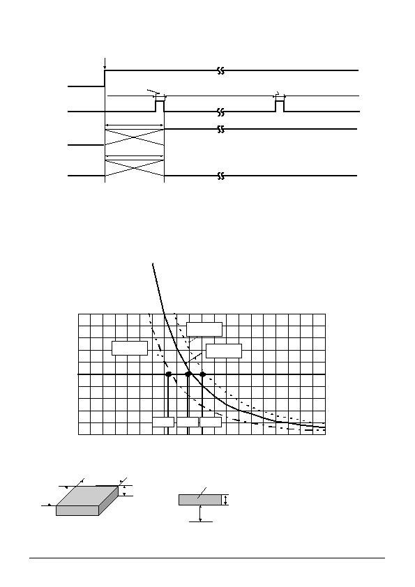
螴ntermittent Operation at Power ON
The bipolar detection Hall IC adopts an intermittent operation method in detecting the magnetic field during startup, as
shown in Fig. 69. It outputs to the appropriate terminal based on the detection result and maintains the output condition
during the standby period. The time from power ON until the end of the initial startup period is an indefinite interval, but it
cannot exceed the maximum period, 100ms. To accommodate the system design, the Hall IC output read should be
programmed within 100ms of power ON, but after the time allowed for the period ambient temperature and supply voltage.
;BD7411G dont adopts an intermittent operation method.
螹agnet Selection
Of the two representative varieties of permanent magnet, neodymium generally offers greater magnetic power per volume
than ferrite, thereby enabling the highest degree of miniaturization, Thus, neodymium is best suited for small equipment
applications. Fig. 70 shows the relation between the size (volume) of a neodymium magnet and magnetic flux density. The
graph plots the correlation between the distance (L) from three versions of a 4mm X 4mm cross-section neodymium magnet
(1mm, 2mm, and 3mm thick) and magnetic flux density. Fig. 71 shows Hall IC detection distance a good guide for
determining the proper size and detection distance of the magnet. Based on the BU52011HFV, BU52015GUL operating
point max 5.0 mT, the minimum detection distance for the 1mm, 2mm and 3mm magnets would be 7.6mm, 9.22mm, and
10.4mm, respectively. To increase the magnets detection distance, either increase its thickness or sectional area.
Magnet material: NMX-44CH
Maker: Hitachi Metals.,LTD
0
1
2
3
4
5
6
7
8
9
10
0
2
4
6
8
10
12
14
16
18
20
Magnet Hall IC distance L [mm]
Fig.71 Magnet Dimensions and Flux Density Measuring Point
X=Y=4mm
t=1mm,2mm,3mm
X
t
Y
&Flux density measuring point
L: Variable
t
Magnet size
Magnet
VDD
Startup time
Standby time
Standby time
Startup time
(Intermittentaction)
Indefinite
interval
OUT
(No magnetic
field present)
Indefinite
interval
OUT
(Magnetic
field present)
Low
High
Supply current
Fig.69
Power ON
10.4mm
7.6mm
t=3mm
t=1mm
t=2mm
9.2mm
Fig.70
相关PDF资料 |
PDF描述 |
|---|---|
| BU52003GUL-E2 | IC HALL EFFECT SW BIPO VCSP50L1 |
| BU52014HFV-TR | IC HALL EFFECT SW BIPO HVSOF5 |
| BU52040HFV-TR | IC HALL EFFECT BIPO LATCH HVSOF5 |
| D6B-2P | SENSR TILT 35-65DEG 1MA SMD GUL |
| D7E-3 | SENSOR TILT 50-80DEG 0.1A GRY |
相关代理商/技术参数 |
参数描述 |
|---|---|
| BU52002GUL | 制造商:ROHM 制造商全称:Rohm 功能描述:Unipolar Detection Hall ICs |
| BU52002GUL_10 | 制造商:ROHM 制造商全称:Rohm 功能描述:Unipolar Detection Hall ICs |
| BU52002GUL_1008 | 制造商:ROHM 制造商全称:Rohm 功能描述:Unipolar Detection Hall ICs |
| BU52002GUL-E2 | 功能描述:板机接口霍耳效应/磁性传感器 Magnetic Sensor 2.4-3.3V; 50mS RoHS:否 制造商:Honeywell 类型:Bipolar Hall-Effect Digital Position Sensor 工作电源电压:3 V to 24 V 电源电流:3.5 mA 最大输出电流:20 mA 工作点最小值/最大值:5 G, 55 G 最小/最大释放点(Brp):- 55 G, - 5 G 最大工作温度:+ 150 C 安装风格:SMD/SMT 封装 / 箱体:SOT-23 |
| BU52003GUL | 制造商:ROHM 制造商全称:Rohm 功能描述:Unipolar Detection Hall ICs |
发布紧急采购,3分钟左右您将得到回复。