- 您现在的位置:买卖IC网 > PDF目录298892 > BX80526F650256E (INTEL CORP) 32-BIT, 650 MHz, MICROPROCESSOR, PPGA370 PDF资料下载
参数资料
| 型号: | BX80526F650256E |
| 厂商: | INTEL CORP |
| 元件分类: | 微控制器/微处理器 |
| 英文描述: | 32-BIT, 650 MHz, MICROPROCESSOR, PPGA370 |
| 封装: | FCPGA2-370 |
| 文件页数: | 14/94页 |
| 文件大小: | 1014K |
| 代理商: | BX80526F650256E |
第1页第2页第3页第4页第5页第6页第7页第8页第9页第10页第11页第12页第13页当前第14页第15页第16页第17页第18页第19页第20页第21页第22页第23页第24页第25页第26页第27页第28页第29页第30页第31页第32页第33页第34页第35页第36页第37页第38页第39页第40页第41页第42页第43页第44页第45页第46页第47页第48页第49页第50页第51页第52页第53页第54页第55页第56页第57页第58页第59页第60页第61页第62页第63页第64页第65页第66页第67页第68页第69页第70页第71页第72页第73页第74页第75页第76页第77页第78页第79页第80页第81页第82页第83页第84页第85页第86页第87页第88页第89页第90页第91页第92页第93页第94页
Datasheet
21
Pentium III Processor for the PGA370 Socket at 500 MHz to 1.13 GHz
NOTES:
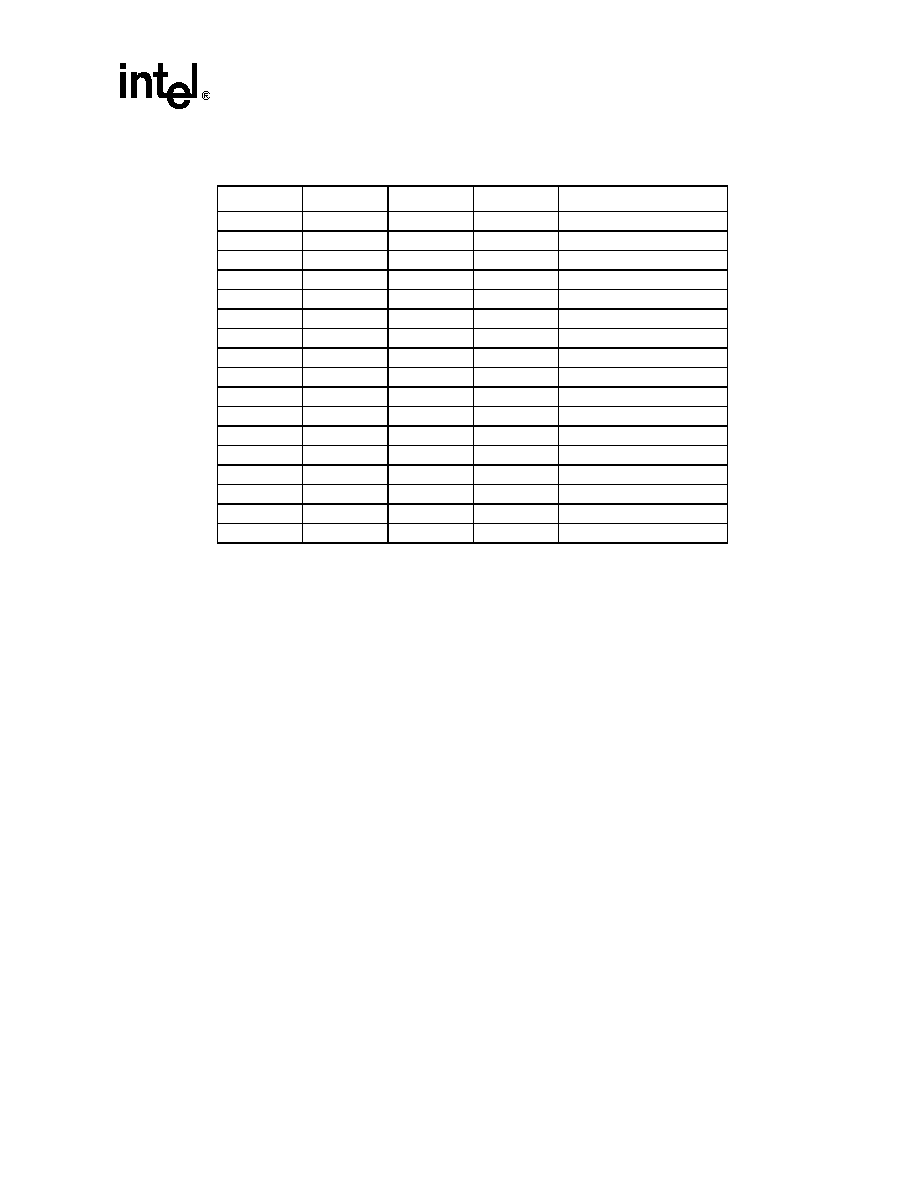
1. 0 = Processor pin connected to VSS.
2. 1 = Open on processor; may be pulled up to TTL VIH on baseboard.
3. To ensure a system is ready for the Pentium III and Celeron processors, the values in BOLD in Table 2 should
be supported.
Note that the ‘1111’ (all opens) ID can be used to detect the absence of a processor core in a given
socket as long as the power supply used does not affect these lines. Detection logic and pull-ups
should not affect VID inputs at the power source (see Section 7.0).
The VID pins should be pulled up to a TTL-compatible level with external resistors to the power
source of the regulator only if required by the regulator or external logic monitoring the VID[3:0]
signals. The power source chosen must be guaranteed to be stable whenever the supply to the
voltage regulator is stable. This will prevent the possibility of the processor supply going above the
specified VCCCORE in the event of a failure in the supply for the VID lines. In the case of a DC-to-
DC converter, this can be accomplished by using the input voltage to the converter for the VID line
pull-ups. A resistor of greater than or equal to 10 k
maybe usedtoconnect the VID signalstothe
converter input. Note that no changes have been made to the physical connector or pin definitions
between the Intel-enabled VRM 8.2 and VRM 8.4 specifications.
Note:
VRM 8.5 specification uses five VID pin assignments VID[3:0, 25mV] and it is not compatible
with VRM 8.4. Some Pentium III processors with CPUID 068xh are capable of supporting both
VRM 8.4 and VRM 8.5 specifications. Please refer to the Pentium III Specification Update for a
listing of processors that support both VRM specifications.
Table 2.
Voltage Identification Definition 1, 2
VID3
VID2
VID1
VID0
VccCORE
1111
1.30
1110
1.35
1101
1.40
1100
1.45
1011
1.50
1010
1.55
1001
1.603
1000
1.653
0111
1.703
0110
1.753
0101
1.80 3
0100
1.85 3
0011
1.90 3
0010
1.95 3
0001
2.00 3
0000
2.05 3
1111
No Core
相关PDF资料 |
PDF描述 |
|---|---|
| BX80526F750256E | 32-BIT, 750 MHz, MICROPROCESSOR, PPGA370 |
| BX80526F850256E | 32-BIT, 850 MHz, MICROPROCESSOR, PPGA370 |
| BX80526C866256E | 32-BIT, 866 MHz, MICROPROCESSOR, PPGA370 |
| BX80526F733256E | 32-BIT, 733 MHz, MICROPROCESSOR, PPGA370 |
| BX80547RE2533CN | 32-BIT, 2530 MHz, MICROPROCESSOR, PBGA775 |
相关代理商/技术参数 |
参数描述 |
|---|---|
| BX80526H800256E827304 | 制造商:Intel 功能描述:MPU PENTIUM III CISC 64BIT 0.18UM 800MHZ 370PIN FCPGA - Boxed Product (Development Kits) |
| BX80526KY7002M | 制造商:Intel 功能描述:MPU PENTIUM III XEON 64-BIT 0.18UM 700MHZ - Boxed Product (Development Kits) |
| BX80526KY9002M | 制造商:Intel 功能描述:MPU PENTIUM III XEON 64-BIT 0.18UM 900MHZ - Boxed Product (Development Kits) |
| BX80528JK150GR | 制造商:未知厂家 制造商全称:未知厂家 功能描述:Microprocessor |
| BX80528JK150GR2 | 制造商:未知厂家 制造商全称:未知厂家 功能描述:Microprocessor |
发布紧急采购,3分钟左右您将得到回复。