- 您现在的位置:买卖IC网 > Datasheet目录318 > CAT4106YP-T2 (ON Semiconductor)IC LED DVR 4CH BOOST 16TSSOP Datasheet资料下载
参数资料
| 型号: | CAT4106YP-T2 |
| 厂商: | ON Semiconductor |
| 文件页数: | 11/15页 |
| 文件大小: | 0K |
| 描述: | IC LED DVR 4CH BOOST 16TSSOP |
| 标准包装: | 1 |
| 恒定电流: | 是 |
| 拓扑: | PWM,升压(升压) |
| 输出数: | 4 |
| 内部驱动器: | 是 |
| 类型 - 主要: | 汽车,背光,通用型 |
| 频率: | 700kHz ~ 1.3MHz |
| 电源电压: | 3 V ~ 5.5 V |
| 输出电压: | 36V |
| 安装类型: | 表面贴装 |
| 封装/外壳: | 16-TSSOP(0.173",4.40mm)裸露焊盘 |
| 供应商设备封装: | 16-TSSOP-EP |
| 包装: | 标准包装 |
| 工作温度: | -40°C ~ 85°C |
| 其它名称: | CAT4106YP-T2OSDKR |
�� �
�
�CAT4106�
�R6� +� R7�
�*� 1�
�R4� +� R5�
�*� 1�
�V� L�
�The� external� resistor� R6� value� needed� to� set� a� VFMIN�
�level� of� 18� V� is� calculated� as� follows:�
�18 V�
�1.2� V�
�For� R7� =� 20� k� W� ,� R6� =� 280� k� W� .�
�Setting� VFMAX� Level� (Open� ?� LED)�
�The� VFMAX� level� represents� the� maximum� level� expected�
�for� the� LED� string� voltage� “window� of� operation”.� This�
�voltage� setting� is� based� on� the� number� of� series� LEDs� being�
�used� and� the� expected� maximum� V� F� during� normal� operation.�
�Example:� Consider� a� string� of� 6� LEDs� in� series,� with� each�
�LED� having� a� V� F� range� of� 3.5� V� ±� 0.5� V.� Since� the�
�maximum� V� F� of� each� LED� is� 4.0� V,� the� overall� maximum�
�expected� string� voltage� would� be� 24� V.� Any� string� voltage�
�which� appears� greater� than� 24� V� would� be� considered� as�
�containing� an� open� ?� circuit� in� one� or� more� of� the� series�
�LEDs.� The� external� resistor� R4� value� needed� to� set� a�
�VFMAX� level� of� 24� V� is� calculated� as� follows:�
�24 V�
�1.2� V�
�During� PWM� dimming,� the� recommended� minimum�
�pulse� width� interval� (either� High� or� Low)� is� 0.2� m� s.� The�
�recommended� maximum� pulse� width� during� PWM�
�dimming� is� 2.5� ms,� however� this� only� applies� to� the� Low�
�pulse� interval.� Pulse� durations� extending� past� 2.5� ms� may�
�cause� the� device� to� enter� full� shutdown� mode.� The� LED�
�channel� response� time� is� much� longer� if� the� device� has� been�
�in� shutdown� mode.�
�For� most� applications,� a� maximum� dimming� resolution�
�can� be� achieved� with� PWM� clock� frequencies� in� the� range�
�of� 100� Hz� to� 2� kHz.� Pulse� width� intervals� of� 1� m� s,� allows� up�
�to� 1000:1� dimming� ratio� at� 1� kHz� PWM� frequency.�
�One� or� Two� LED� String� Applications�
�The� CAT4106� can� be� used� to� drive� one� or� two� strings� of�
�LEDs� by� connecting� together� some� LED� pins.� Also� for�
�applications� requiring� LED� current� greater� than� 175� mA,�
�LED� channels� can� be� tied� together,� assuming� the� supply� is�
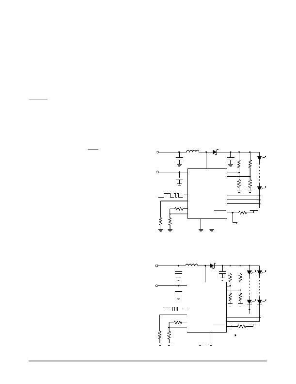
�suitable� to� drive� the� load.� Figure� 27� shows� a� typical�
�application� for� driving� a� single� string� of� LEDs.� The� LED�
�current� is� equal� to� four� times� the� channel� current.�
�L� D�
�For� R5� =� 20� k� W� ,� R4� =� 380� k� W� .�
�In� normal� operation,� the� LED� string� which� has� the� largest�
�V� F� will� be� used� to� set� the� VCTRL/VFB� voltage� levels.� If� the�
�largest� string� voltage� tries� to� exceed� VFMAX� setting,� it� will�
�no� longer� be� allowed� to� control� the� voltage� level� of�
�V� IN�
�C2�
�C1�
�VIN�
�C3�
�SW� VFMAX�
�VFMIN�
�CAT4106�
�R4�
�R5�
�R6�
�R7�
�RSET�
�VCTRL�
�FB� GND� PGND�
�VCTRL/VFB� (i.e.� it� will� be� ignored)� and� subsequently� the�
�next� largest� LED� string� voltage� will� then� be� used� in� the�
�control� loop.� All� remaining� functional� LED� channels� will�
�continue� to� operate� as� normal.� If� a� disconnected� LED� string�
�is� reconnected,� the� FAULT� flag� remains� on� and� the� channel�
�disabled� until� the� device� has� been� re� ?� enabled� with� the� EN�
�pin� going� from� low� to� high.�
�If� all� LED� channels� are� detected� as� being� open� ?� circuit,�
�OFF...� ON...� DIM...�
�R2�
�R1� R3�
�EN/PWM� LED1�
�LED2�
�LED3�
�LED4�
�FAULT�
�V� IN�
�R8�
�LED� Fault� Detection�
�(open� drain� pull� ?� down)�
�then� the� boost� converter� will� limit� the� output� voltage� to� the�
�VFMAX� setting.� This� eliminates� the� need� for� an� external�
�protection� zener.�
�Figure� 27.� Application� Circuit� for� One� LED� String�
�Figure� 28� shows� a� typical� application� for� driving� two�
�strings� of� LEDs.� The� LED� current� is� equal� to� two� times� the�
�Enable� and� PWM� Dimming� Control�
�EN/PWM� input� signal� provides� two� independent�
�channel� current.�
�V� L�
�L�
�D�
�functions.� The� first� function� is� to� enable� and� disable� the�
�entire� device.� The� second� function� is� to� apply� PWM�
�dimming� on� the� output� channels� while� the� chip� remains� fully�
�enabled.� Applying� logic� high� on� the� EN/PWM� input� will�
�power� up� the� device.� The� device� will� continue� to� remain�
�powered� up,� even� in� the� presence� of� PWM� signals� being�
�V� IN�
�C2�
�C1�
�VIN�
�C3�
�SW� VFMAX�
�VFMIN�
�CAT4106�
�R4�
�R5�
�R6�
�R7�
�RSET�
�FB� GND� PGND�
�applied.� To� disable� the� device� into� complete� system�
�shutdown� mode,� a� logic� low� must� be� applied� to� the�
�EN/PWM� input� for� typically� 5� ms.�
�The� duty� cycle� applied� at� the� EN/PWM� is� directly� applied�
�to� all� the� output� channels.� Each� time� the� input� is� taken� low,�
�all� output� channels� will� immediately� be� switched� off� and� the�
�channels� will� resume� normal� operation� when� the� PWM� is�
�taken� back� high.� The� response� time� of� the� channels� when�
�switching� ON� or� OFF� is� typically� 0.2� m� s.�
�OFF...� ON...� DIM...�
�EN/PWM� LED1�
�LED2�
�R2� LED3�
�VCTRL� LED4�
�FAULT� V� IN�
�R8�
�R1� R3�
�LED� Fault� Detection�
�(open� drain� pull� ?� down)�
�Figure� 28.� Application� Circuit� for� Two� LED� Strings�
�http://onsemi.com�
�11�
�相关PDF资料 |
PDF描述 |
|---|---|
| CAT4109V-GT2 | IC LED DRIVER RGB 16-SOIC |
| CAT4134HV2-T2 | IC LED DRVR BKLGHT FLASH 12-TDFN |
| CAT4137TD-T3 | IC LED DRVR WHITE BCKLGHT TSOT-5 |
| CAT4139TD-GT3 | IC LED DRVR WHITE BCKLGT TSOT-5 |
| CAT4237TD-T3 | IC LED DRVR WHITE BCKLGHT TSOT-5 |
相关代理商/技术参数 |
参数描述 |
|---|---|
| CAT4107HV4-GT2 | 制造商:ON Semiconductor 功能描述: |
| CAT4109 | 制造商:ONSEMI 制造商全称:ON Semiconductor 功能描述:3-Channel Constant-Current RGB LED Driver with Individual PWM Dimming |
| CAT4109VG | 制造商:Catalyst Semiconductor 功能描述: |
| CAT4109V-GT2 | 功能描述:LED照明驱动器 LED Driver 3ch RGB PWM RoHS:否 制造商:STMicroelectronics 输入电压:11.5 V to 23 V 工作频率: 最大电源电流:1.7 mA 输出电流: 最大工作温度: 安装风格:SMD/SMT 封装 / 箱体:SO-16N |
| CAT4-11E | 制造商:ABB Control 功能描述:CONTACT BLKAUXFRNT1NO+1NC |
发布紧急采购,3分钟左右您将得到回复。