- 您现在的位置:买卖IC网 > Datasheet目录318 > CAV4201TD-GT3 (ON Semiconductor)IC LED DVR 350MA STP-DN TSOT23-5 Datasheet资料下载
参数资料
| 型号: | CAV4201TD-GT3 |
| 厂商: | ON Semiconductor |
| 文件页数: | 10/12页 |
| 文件大小: | 0K |
| 描述: | IC LED DVR 350MA STP-DN TSOT23-5 |
| 标准包装: | 3,000 |
| 系列: | * |
�� �
�
�CAV4201�
�300�
�250�
�200�
�150�
�100�
�50�
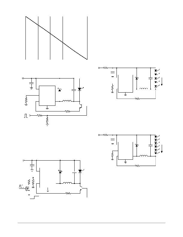
�Operation� from� High� Supply� Voltage� Above� 14� V�
�For� operation� from� a� supply� voltage� above� 14� V,� it� is�
�recommended� to� have� a� slew� rate� of� 1� m� s� or� more� for� every�
�5� V� increase� in� VBAT� supply.� When� using� a� high� supply�
�voltage� of� 24� V,� a� 1� W� or� 2� W� resistor� in� series� with� the� supply,�
�as� shown� on� Figure� 28,� is� recommended� to� limit� the� slew� rate�
�of� the� supply� voltage.� A� 4.7� m� F� minimum� ceramic� capacitor�
�is� placed� between� the� VBAT� pin� and� ground.� The�
�combination� of� the� series� resistor� R3� and� input� capacitor� C1�
�acts� as� a� low� pass� filter� limiting� the� excessive� in� ?� rush�
�currents� and� overvoltage� transients� which� would� otherwise�
�0�
�100�
�80�
�60�
�40�
�20�
�0�
�occur� during� “hot� ?� plug”� conditions,� thereby� protecting� the�
�CAV4201� driver.�
�DUTY� CYCLE� [%]�
�Figure� 25.� LED� Current� vs.� Duty� Cycle�
�VBAT� R3�
�24� V� 1� W� C1�
�VBAT�
�4.7� m� F�
�VBAT�
�D1�
�C2�
�5V�
�4.7� m� F�
�L�
�10� k� W� CTRL� SW�
�GND�
�33� m� H�
�12� V� C1�
�4.7� m� F�
�R1�
�10� k� W�
�PWM�
�control�
�0V�
�VBAT�
�CAV4201�
�RSET�
�CTRL� SW�
�GND�
�R4�
�1� k� W� R5�
�47� k� W�
�D�
�C2�
�10� m� F�
�L�
�22� m� H�
�R2�
�1� k� W�
�Q1�
�NPN�
�CAV4201�
�RSET�
�R1�
�300� mA�
�R1�
�1� k� W�
�Figure� 28.� 24� V� Application� with� 5� LEDs�
�Operation� from� High� Supply� Voltage� of� 36� V�
�When� powering� from� a� high� supply� voltage� of� 36� V,� a� 2� W�
�resistor� in� series� with� the� supply� is� recommended,� as� shown�
�on� Figure� 29,� to� limit� the� slew� rate� of� the� supply� voltage.�
�Figure� 26.� Circuit� for� PWM� on� CTRL�
�PWM� on� RSET� Pin�
�Another� dimming� method� is� to� place� in� parallel� to� R1�
�Inductor� value� should� be� 33� m� H� or� higher.�
�VBAT� R3�
�36� V� 2� W� C1�
�SW�
�another� resistor� with� a� FET� in� series,� as� shown� on� Figure� 27.�
�R1� sets� the� minimum� LED� current� corresponding� to� 0%� duty�
�cycle.� The� combined� resistor� of� R1� and� Rmax� sets� the�
�maximum� LED� current� corresponding� to� 100%� duty� cycle.�
�VBAT�
�4.7� m� F�
�R1�
�10� k� W�
�VBAT�
�CAV4201�
�RSET�
�CTRL�
�GND�
�D1� C2�
�2.2� m� F�
�L�
�47� m� H�
�300� mA�
�13� V� C1�
�R2�
�4.7� m� F�
�Rmax� R1�
�PWM�
�control�
�OFF� ON�
�VBAT�
�CAV4201�
�RSET�
�CTRL� SW�
�GND�
�D�
�C2�
�10� m� F�
�L�
�22� m� H�
�R2�
�1� k� W�
�Q1�
�NPN�
�1� k� W�
�Figure� 29.� 36� V� Application� with� 6� LEDs�
�Parallel� Configuration� for� Driving� LEDs� Beyond�
�350� mA�
�Several� CAV4201� devices� can� be� connected� in� parallel� for�
�driving� LEDs� with� current� in� excess� of� 350� mA.� The�
�CAV4201� driver� circuits� are� connected� to� the� same� LED�
�cathode.� Figure� 30� shows� the� application� schematic� for�
�Figure� 27.� Circuit� for� PWM� on� RSET�
�A� resistor� value� for� R1� of� less� than� 90� k� W� is� recommended�
�to� provide� better� accuracy.�
�driving� 1� A� into� one� LED� with� three� CAV4201� connected� in�
�parallel.� Each� CAV4201� is� driving� the� LED� with� a� current�
�set� by� its� RSET� resistor.� The� resulting� LED� current� is� equal�
�to� the� sum� of� each� driver� current.�
�http://onsemi.com�
�10�
�相关PDF资料 |
PDF描述 |
|---|---|
| CB-1377 | PANEL ALUMINUM CHASSIS |
| CBC5300-24C | ENERCHIP EH CBC5300 MODULE |
| CC-ACC-MX51-ETM | ADAPTER TRACE ETM/ETB JTAG |
| CDBMCU-DEBUG | EVAL BD FOR DSP CS48X & CS49X |
| CEL2MUSB | E2GO CELL PHONE CHARGER USB |
相关代理商/技术参数 |
参数描述 |
|---|---|
| CAV424 | 制造商:未知厂家 制造商全称:未知厂家 功能描述:Converter IC for Capacitive Signals |
| CAV444 | 制造商:AD 制造商全称:Analog Devices 功能描述:C/V transmitter IC with adjustable output voltage for capacitive input signals |
| CAV-5.0-1.0 | 制造商:TALEMA 制造商全称:TALEMA 功能描述:Common Mode Toroidal Chokes |
| CAV-5.0-1.5 | 制造商:TALEMA 制造商全称:TALEMA 功能描述:Common Mode Toroidal Chokes |
| CAV-5.0-10 | 制造商:TALEMA 制造商全称:TALEMA 功能描述:Common Mode Toroidal Chokes |
发布紧急采购,3分钟左右您将得到回复。