- 您现在的位置:买卖IC网 > PDF目录257720 > CG3040-9 3-OUTPUT 25 W DC-DC REG PWR SUPPLY MODULE PDF资料下载
参数资料
| 型号: | CG3040-9 |
| 元件分类: | 电源模块 |
| 英文描述: | 3-OUTPUT 25 W DC-DC REG PWR SUPPLY MODULE |
| 文件页数: | 12/16页 |
| 文件大小: | 283K |
| 代理商: | CG3040-9 |
Board Mountable
DC-DC Converters
G Series
Edition 5/5.2000
5/16
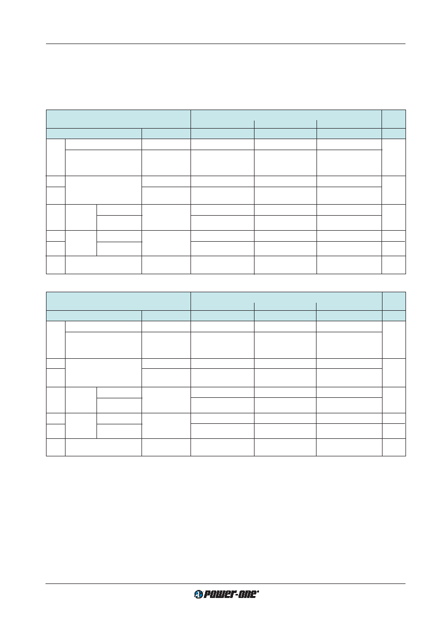
Electrical Output Data
General conditions:
–
TA = 25
°C, unless T
C is specified.
– Connector pins i (inhibit) and Vi– interconnected
– R input not connected.
Table 4a: Output data for dual output modules BG...CG 3020-7
Output
BG...CG 3020-7
Output 1
Output 2
Output 3
Characteristics
Conditions
min
typ
max
min
typ
max
min
typ
max
Unit
Uo
Output voltage
Ui nom, Io nom
5.0
5.05
5.1
12.15
12.6
12.85
–12.85 –12.6 –12.15
Static output voltage
TC min...TC max
5
5.1
11.95
13.25
–13.25
–11.95
Ui nom
Io = 0...Io max 1
Io nom Output current
Ui nom
2
0.6
–0.6
A
Io max
only one output
5
2
–2
loaded
uo
Output
Switching freq.
Ui nom, Io nom
25
50
mVpp
voltage
Total
IEC/EN 61204 2
50
100
noise
BW = 20 MHz
uo d
Dynamic 3 Voltage limits
Ui min...Ui max
4.8
5.25
11.35
13.85
–13.85
–11.35
V
t d
load
Recovery time
Io nom 1/2 Io nom
100
s
regulation
IEC/EN 61204
Uo adj Output voltage
Uo nom setting
60...110
60..100
% of
adjustment range
via R input
Uo nom
Table 4b: Output data for dual output modules BG...CG 3040-7
Output
BG...CG 3040-7
Output 1
Output 2
Output 3
Characteristics
Conditions
min
typ
max
min
typ
max
min
typ
max
Unit
Uo
Output voltage
Ui nom, Io nom
5.0
5.05
5.1
15.0
15.4
15.7
–15.7 –15.4
–15.0
V
Static output voltage
TC min...TC max
5
5.1
14.6
16.2
–16.2
–14.6
Ui nom
Io = 0...Io max 1
Io nom Output current
Ui nom
2
0.5
–0.5
A
Io max
only one output
5
1.6
–1.6
loaded
uo
Output
Switching freq.
Ui nom, Io nom
25
50
mVpp
voltage
Total
IEC/EN 61204 2
50
100
noise
BW = 20 MHz
uo d
Dynamic 3 Voltage limits
Ui min...Ui max
4.8
5.25
13.8
17.0
–17.0
–13.8
V
t d
load
Recovery time
Io nom 1/2 Io nom
100
s
regulation
IEC/EN 61204
Uo adj Output voltage
Uo nom setting
60...110
60..100
% of
adjustment range
via R input
Uo nom
1 Power difference between one auxiliary output and main output <12 W. Total output power
≤P
o nom.
2 See: Technical Information: Measuring and Testing.
3 Load current change for specific output. Other outputs loaded with Io nom.
Output Current Limitation
The G series modules have a current limitation allowing
free choice of load distribution between all outputs, up to a
total current:
Uo2 nom
Uo3 nom
Io1 + ––––––– Io2 + ––––––– Io3
≤ I
o1 max
Uo1 nom
In overload all output voltages are simultaneously reduced.
Output Overvoltage Protection
The outputs of the unit are protected against overvoltages
by a second fully independent control loop which disables
the unit. The unit tries to restart after a short time (5 ms).
The main purpose of this second control loop is to protect
against possible overvoltages which could occur due to a
failure in the normal feedback control loop. The second con-
trol loop does not protect the unit against externally applied
overvoltages.
相关PDF资料 |
PDF描述 |
|---|---|
| CAT1027ZI-28-T3 | 2-CHANNEL POWER SUPPLY MANAGEMENT CKT, PDSO8 |
| CAT1021LE-28TE13 | 1-CHANNEL POWER SUPPLY MANAGEMENT CKT, PDIP8 |
| CAT1021LE-42TE13 | 1-CHANNEL POWER SUPPLY MANAGEMENT CKT, PDIP8 |
| CAT1021LI-30TE13 | 1-CHANNEL POWER SUPPLY MANAGEMENT CKT, PDIP8 |
| CAT1022LI-30 | 1-CHANNEL POWER SUPPLY MANAGEMENT CKT, PDIP8 |
相关代理商/技术参数 |
参数描述 |
|---|---|
| CG304NM | 制造商:Hubbell Wiring Device-Kellems 功能描述:STR MALE NM DCG, .187-.250, 3/8 W/MESH |
| CG304-REF | 功能描述:REPLACEMENT REFERENCE FILMS FOR 制造商:flir 系列:* 零件状态:在售 标准包装:1 |
| CG305NM | 制造商:HUBBELL 功能描述:STR MALE NM DCG, .250-.312", 3/8" W/MESH 制造商:Hubbell Premise Wiring 功能描述:STR MALE NM DCG, .250-.312", 3/8" W/MESH 制造商:Hubbell Wiring Device-Kellems 功能描述:STR MALE NM DCG, .250-.312, 3/8 W/MESH |
| CG306NM | 制造商:Hubbell Wiring Device-Kellems 功能描述:STR MALE NM DCG, .312-.375, 3/8 W/MESH |
| CG31.0 | 制造商:Littelfuse 功能描述:GDT 1.0KV NOMINAL |
发布紧急采购,3分钟左右您将得到回复。