- 您现在的位置:买卖IC网 > PDF目录257720 > CG3040-9 3-OUTPUT 25 W DC-DC REG PWR SUPPLY MODULE PDF资料下载
参数资料
| 型号: | CG3040-9 |
| 元件分类: | 电源模块 |
| 英文描述: | 3-OUTPUT 25 W DC-DC REG PWR SUPPLY MODULE |
| 文件页数: | 7/16页 |
| 文件大小: | 283K |
| 代理商: | CG3040-9 |
Board Mountable
DC-DC Converters
G Series
Edition 5/5.2000
15/16
Output Voltage Monitor
Option D also includes an extended monitoring and diag-
nostic circuitry which continuously monitors all output
voltages and compares them with their high and low thresh-
old values. The circuit can also be used to check the con-
verter for correct function prior to e.g. a general system
check-up in avionic applications or for identification of pos-
sible failures.
The /FAIL output is a failure indicator which can deliver ei-
ther a boolean type or a serial type message. The type of
serial message that will be generated depends upon the
level and chronology applied to /SRQ and /FAIL. The serial
link is asynchronous, with one start bit (low level), 8 data
bits and one stop bit (high level), transmitting at 9600 bauds
±2%.
/FAIL
The /FAIL signal is an open collector input/output allowing
bidirectional communication. It has an internal pull-up resis-
tor of 4.7 k
typ. connected to Vo1+.
/SRQ
The /SRQ signal is a Schmitt-Trigger input with an internal
pull-up resistor of 6.8 k
typ. connected to Vo1+.
Table 19: Input/output data of /FAIL and /SRQ
Parameter Conditions
min.
max.
Units
Isink /FAIL
U/FAIL <0.6 V
48
mA
U/FAIL High
/FAIL = Input
0.7
Uo1
V
U/FAIL Low
0.3
Uo1
U/SRQ High
0.7
Uo1
U/SRQ Low
0.3
Uo1
Important: No voltage higher than
Uo1 should be applied
to /FAIL and /SRQ otherwise the unit may be damaged.
There are 4 possible modes for the monitoring circuit/
serial link.
– Idle state (/FAIL = static failure indicator)
– Transmission of Failure Identification Register (FIR)
– Transmission of Self Test Result
– Programming of the Failure Reporting Mask (FRM)
Idle State (/SRQ high)
In the idle state the /FAIL output is a static failure indicator
with the possibility to mask reported failures. (See:
Pro-
gramming of the FRM.)
If one of the monitored output voltages goes outside of its
threshold values or in the case of an overload or malfunc-
tion of the converter, the corresponding bit (according to
table
Bit Code of FIR) is cleared in the Failure Identification
Register (FIR). If the corresponding bit in the Failure Re-
porting Mask (FRM) is programmed for reporting, the
/FAIL output is set to low.
All bits which are cleared in the FIR and have the corre-
sponding bit programmed in the FRM will be erased 25 ms
after the disappearance of the last failure with reporting
enabled or last continuous idle state, whichever occurs last.
This will result in /FAIL going high. The bits of the FIR whose
corresponding bits in the FRM are at a low level (no report-
ing) will remain unchanged.
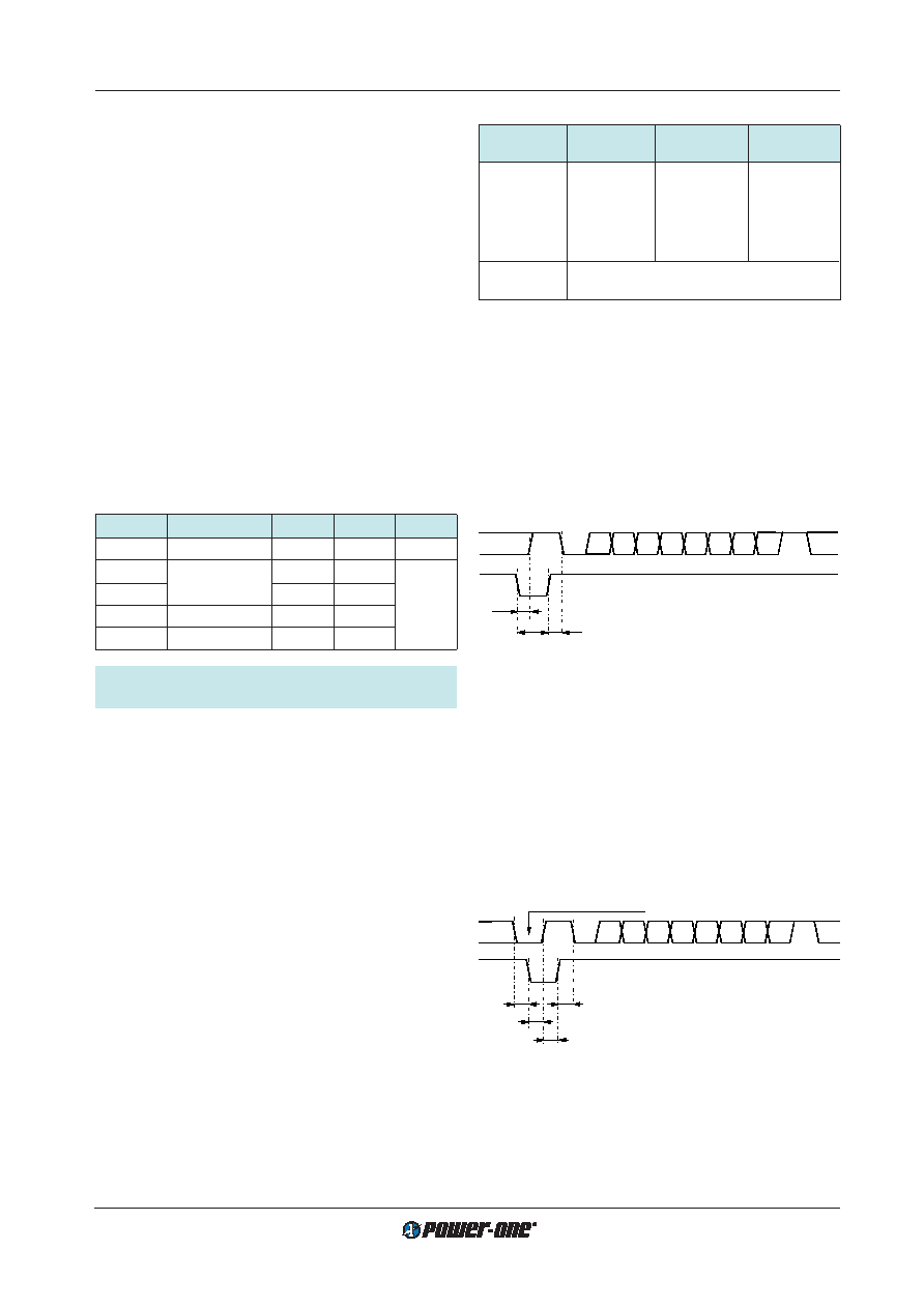
Transmission of Failure Identification Register (FIR)
The contents of the Failure Identification Register will be
transmitted to the user whenever the /SRQ is pulsed low.
/SRQ needs to be kept low for at least T2 (see figure:
Trans-
mission of FIR). After T1 /FAIL will change to high state.
When /SRQ is taken high, the transmission of the FIR starts
after T3. Its content is the one which at the time /SRQ was
taken low. The bits are coded according to table:
Bit Code
of FIR. After the transmission of the FIR the circuit returns
to idle state.
Table 20: Bit Code of Failure Identification Register (FIR)
Bit State
Conditions
Limit min.
Limit max.
[% of
Uo ref] 1
[% of
Uo ref] 1
Bit 0 = 0
Uo1 < limit
90
95
Bit 1 = 0
Uo1 > limit
105
110
Bit 2 = 0
Uo2 < limit
85
90
Bit 3 = 0
Uo2 > limit
110
115
Bit 4 = 0
Uo3 < limit
115
110
Bit 5 = 0
Uo3 > limit
90
85
Bit 6 = 0
overload condition
Bit 7 = 0
malfunction of the converter
1 The limits won't track the output voltages if adjusted by means
of the R pin.
Uo ref = 5 V resp. 12.5 V resp. 15 V.
Transmission of Self Test Results
The diagnostic circuit has the capability to perform a self
test on its own diagnostic functions in order to increase the
detected failure rate. All possible defined failures will be in-
ternally simulated. The user can check the recognition of
the failures by the setting of the bits in the serial message.
All bits should be in the high state for correct functioning of
the circuit. (See table:
Bit Code of FIR.)
To enter the self test routine the user should take the /SRQ
signal low and force the /FAIL signal to low state for at least
T5. The self test result is transmitted at a time T7 after the
/SRQ was taken high.
ST B0 B1 B2 B3 B4 B5 B6 B7
S
/FAIL
/SRQ
T2
T3
T1
T1 = max 10
s
T2 = min 20
s
T3 = max 10
s
11015
Fig. 27
Transmission of FIR
After the transmission of the self test the circuit returns into
idle state. If the self test routine detects any failure which is
programmed in the FRM for being reported then /FAIL will
remain low in idle state until the next self test routine is
started.
ST B0 B1 B2 B3 B4 B5 B6 B7 S
/FAIL
/SRQ
T4
T5
T6
T7
T4 = min –10
s 1
T5 = min 20
s
T6 = min 10
s
T7 = max 10
s
11016
forced to low by user
1 The negative value of T4 means that /FAIL can be
forced low latest 10
s after /SRQ was forced low.
Fig. 28
Self test
相关PDF资料 |
PDF描述 |
|---|---|
| CAT1027ZI-28-T3 | 2-CHANNEL POWER SUPPLY MANAGEMENT CKT, PDSO8 |
| CAT1021LE-28TE13 | 1-CHANNEL POWER SUPPLY MANAGEMENT CKT, PDIP8 |
| CAT1021LE-42TE13 | 1-CHANNEL POWER SUPPLY MANAGEMENT CKT, PDIP8 |
| CAT1021LI-30TE13 | 1-CHANNEL POWER SUPPLY MANAGEMENT CKT, PDIP8 |
| CAT1022LI-30 | 1-CHANNEL POWER SUPPLY MANAGEMENT CKT, PDIP8 |
相关代理商/技术参数 |
参数描述 |
|---|---|
| CG304NM | 制造商:Hubbell Wiring Device-Kellems 功能描述:STR MALE NM DCG, .187-.250, 3/8 W/MESH |
| CG304-REF | 功能描述:REPLACEMENT REFERENCE FILMS FOR 制造商:flir 系列:* 零件状态:在售 标准包装:1 |
| CG305NM | 制造商:HUBBELL 功能描述:STR MALE NM DCG, .250-.312", 3/8" W/MESH 制造商:Hubbell Premise Wiring 功能描述:STR MALE NM DCG, .250-.312", 3/8" W/MESH 制造商:Hubbell Wiring Device-Kellems 功能描述:STR MALE NM DCG, .250-.312, 3/8 W/MESH |
| CG306NM | 制造商:Hubbell Wiring Device-Kellems 功能描述:STR MALE NM DCG, .312-.375, 3/8 W/MESH |
| CG31.0 | 制造商:Littelfuse 功能描述:GDT 1.0KV NOMINAL |
发布紧急采购,3分钟左右您将得到回复。