- 您现在的位置:买卖IC网 > PDF目录11818 > CP82C52Z (Intersil)IC UART/BRG 5V 16MHZ 28-PDIP PDF资料下载
参数资料
| 型号: | CP82C52Z |
| 厂商: | Intersil |
| 文件页数: | 18/20页 |
| 文件大小: | 0K |
| 描述: | IC UART/BRG 5V 16MHZ 28-PDIP |
| 标准包装: | 143 |
| 特点: | 单芯片 UART/BRG |
| 通道数: | 1,UART |
| 规程: | RS232C |
| 电源电压: | 4.5 V ~ 5.5 V |
| 带并行端口: | 是 |
| 带故障启动位检测功能: | 是 |
| 带调制解调器控制功能: | 是 |
| 带CMOS: | 是 |
| 安装类型: | 通孔 |
| 封装/外壳: | 28-DIP(0.600",15.24mm) |
| 供应商设备封装: | 28-PDIP |
| 包装: | 管件 |
7
FN2950.3
April 26, 2006
a buffered version of the data seen on the SDI input and is
not a resynchronized output. Also note that normal UART
transmission via the Transmitter Register is disabled when
operating in the Echo mode (see Figure 4). The Loop Test
Mode internally routes transmitted data to the receiver
circuitry for the purpose of self test. The transmit data is
disabled from the SDO output pin. The Receiver Enable bit
gates off the input to the receiver circuitry when in the false
state.
Modem Interrupt Enable will permit any change in modem
status line inputs (CTS, DSR) to cause an interrupt when this
bit is enabled. Bit D7 must always be written to with a logic
zero to insure correct 82C52 operation.
UART Status Register (USR)
The USR provides a single register that the controlling sys
tem can examine to determine if errors have occurred or if
other status changes in the 82C52 require attention. For this
reason, the USR is usually the first register read by the CPU
to determine the cause of an interrupt or to poll the status of
the 82C52.
Three error flags OE, FE and PE report the status of any
error conditions detected in the receiver circuitry. These
error flags are updated with every character received during
reception of the stop bits. The Overrun Error (OE) indicates
that a character in the Receiver Register has been received
and cannot be transferred to the Receiver Buffer Register
(RBR) because the RBR was not read by the CPU. Framing
Error (FE) indicates that the last character received in the
RBR contained improper stop bits. This could be caused by
the absence of the required stop bit(s) or by a stop bit(s) that
was too short to be properly detected. Parity Error (PE)
indicates that the last character received in the RBR
contained a parity error based on the programmed parity of
the receiver and the calculated parity of the received
character data and parity bits.
The Received Break (RBRK) status bit indicates that the last
character received was a break character. A break character
would be considered to be an invalid data character in that
the entire character including parity and stop bits are a logic
zero.
The Modem Status bit is set whenever a transition is
detected on any of the Modem input lines (CTS or DSR). A
subsequent read of the Modem Status Register will show the
state of these two signals. Assertion of this bit will cause an
interrupt (INTR) to be generated if the MIEN and INTEN bits
in the MCR register are enabled.
The Transmission Complete (TC) bit indicates that both the
TBR and Transmitter Registers are empty and the 82C52
has completed transmission of the last character it was
commanded to transmit. The assertion of this bit will cause
an interrupt (INTR) if the INTEN bit in the MCR register is
true.
The Transmitter Buffer Register Empty (TBRE) bit indicates
that the TBR register is empty and ready to receive another
character.
The Data Ready (DR) bit indicates that the RBR has been
loaded with a received character (including Break) and that
the CPU may access this data.
Assertion of the TBRE or DR bits do not affect the INTR logic
and associated INTR output pin since the 82C52 has been
designed to provide separate requests via the DR and TBRE
output pins. If a single interrupt for any status change in the
82C52 is desired this can be accomplished by using an
82C59A Interrupt controller with DR, TBRE, and INTR as
inputs. (See Figure 11).
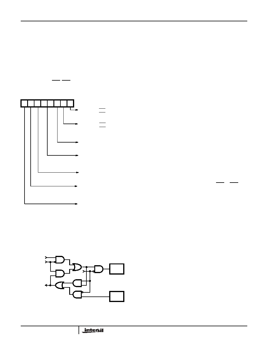
D7 D6 D5 D4 D3 D2 D1 D0
Request
to Send
(RTS)
0 = RTS Output High
1 = RTS Output Low
Data
Terminal
Ready
(DTR)
0 = DTR Output High
1 = DTR Output Low
Interrupt
Enable
(INTEN)
1 = Interrupts Enabled
0 = interrupts Disabled
Mode
Select
00 = Normal
01 = Transmit Break
10 = Echo Mode
11 = Loop Test Mode
Receiver
Enable
(REN)
0 = Not Enabled
1 = Enabled
Modem
Interrupt
Enable
(MIEN)
0 = Not Enabled
1 = Enabled
Must be Set to a Logic 0 for
Normal 82C52 Operation
See Modem Status Register description for a description of
register flag images with respect to output pins.
FIGURE 3. MCR
FIGURE 4. LOOP AND ECHO MODE FUNCTIONALITY
SERIAL DATA
FROM
TRANSMITTER
REGISTER
ECHO MODE
SERIAL DATA
TO RECEIVER
REGISTER
SDO
PIN 15
SDI
PIN 25
LOOP
MODE
82C52
相关PDF资料 |
PDF描述 |
|---|---|
| ATUC128D4-AUR | IC MCU 32BIT 128KB FLASH 48TQFP |
| VI-B72-IW-F2 | CONVERTER MOD DC/DC 15V 100W |
| V24C12H150B2 | CONVERTER MOD DC/DC 12V 150W |
| VI-B71-IX-F3 | CONVERTER MOD DC/DC 12V 75W |
| VI-B71-IX-F2 | CONVERTER MOD DC/DC 12V 75W |
相关代理商/技术参数 |
参数描述 |
|---|---|
| CP82C54 | 功能描述:计时器和支持产品 PERIPH PRG-CNTR 5V 8MHZ 24PDIP COM RoHS:否 制造商:Micrel 类型:Standard 封装 / 箱体:SOT-23 内部定时器数量:1 电源电压-最大:18 V 电源电压-最小:2.7 V 最大功率耗散: 最大工作温度:+ 85 C 最小工作温度:- 40 C 封装:Reel |
| CP82C5410 | 制造商:Harris Corporation 功能描述: |
| CP82C54-10 | 功能描述:计时器和支持产品 PERIPH PRG-CNTR 5V 10MHZ 24PDIP COM RoHS:否 制造商:Micrel 类型:Standard 封装 / 箱体:SOT-23 内部定时器数量:1 电源电压-最大:18 V 电源电压-最小:2.7 V 最大功率耗散: 最大工作温度:+ 85 C 最小工作温度:- 40 C 封装:Reel |
| CP82C54-10Z | 功能描述:计时器和支持产品 W/ANNEAL PERIPH PRG- CNTR 5V 10MHZ 24PDIP RoHS:否 制造商:Micrel 类型:Standard 封装 / 箱体:SOT-23 内部定时器数量:1 电源电压-最大:18 V 电源电压-最小:2.7 V 最大功率耗散: 最大工作温度:+ 85 C 最小工作温度:- 40 C 封装:Reel |
| CP82C54-10Z | 制造商:Intersil Corporation 功能描述:CMOS PROGRAMMABLE INT TIMER SMD 制造商:Intersil Corporation 功能描述:CMOS, PROGRAMMABLE INT TIMER, SMD |
发布紧急采购,3分钟左右您将得到回复。