- 您现在的位置:买卖IC网 > PDF目录10940 > CS42L55-CNZR (Cirrus Logic Inc)IC CODEC STER H-HDPN AMP 36-QFN PDF资料下载
参数资料
| 型号: | CS42L55-CNZR |
| 厂商: | Cirrus Logic Inc |
| 文件页数: | 13/68页 |
| 文件大小: | 0K |
| 描述: | IC CODEC STER H-HDPN AMP 36-QFN |
| 标准包装: | 6,000 |
| 类型: | 立体声音频 |
| 数据接口: | 串行 |
| 分辨率(位): | 24 b |
| ADC / DAC 数量: | 1 / 1 |
| 三角积分调变: | 是 |
| 动态范围,标准 ADC / DAC (db): | 95 / 99 |
| 电压 - 电源,模拟: | 1.65 V ~ 2.71 V |
| 电压 - 电源,数字: | 1.65 V ~ 2.71 V |
| 工作温度: | -40°C ~ 85°C |
| 安装类型: | 表面贴装 |
| 封装/外壳: | 36-QFN |
| 供应商设备封装: | 36-QFN-EP(5x5) |
| 包装: | 带卷 (TR) |
| 配用: | 598-1506-ND - BOARD EVAL FOR CS42L55 CODEC |
第1页第2页第3页第4页第5页第6页第7页第8页第9页第10页第11页第12页当前第13页第14页第15页第16页第17页第18页第19页第20页第21页第22页第23页第24页第25页第26页第27页第28页第29页第30页第31页第32页第33页第34页第35页第36页第37页第38页第39页第40页第41页第42页第43页第44页第45页第46页第47页第48页第49页第50页第51页第52页第53页第54页第55页第56页第57页第58页第59页第60页第61页第62页第63页第64页第65页第66页第67页第68页
MIC3000
Micrel
M9999-101204
20
October 2004
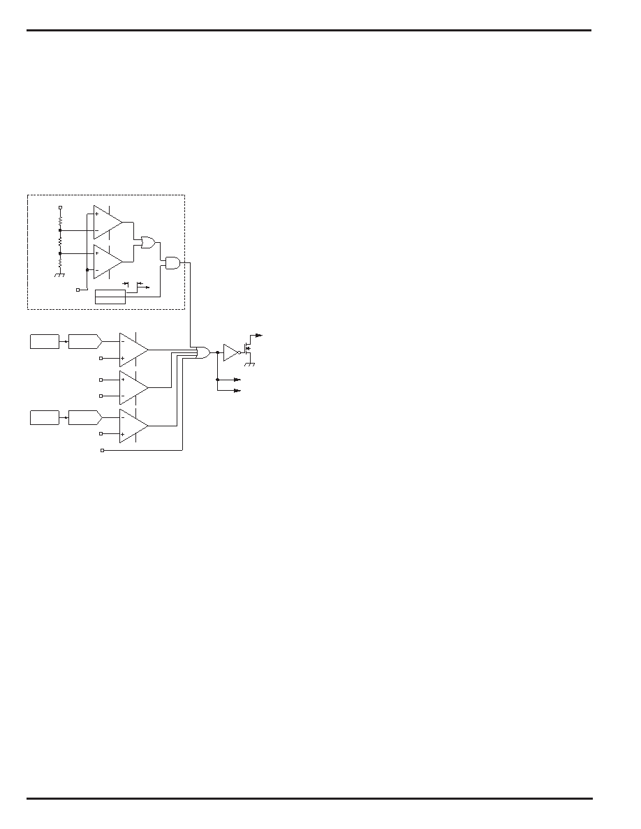
Fault Comparators
In addition to detecting and reporting the events specified in
SFF-8472, the MIC3000 also monitors five fault conditions:
inadequate supply voltage, thermal diode faults, excessive
bias current, excessive transmit power, and APC op-amp
saturation. Comparators monitor these parameters in order
to respond quickly to fault conditions that could indicate link
failure or safety issues, see Figure 8. When a fault is detected,
the laser is shut down and TXFAULT is asserted. Each fault
source may be independently disabled using the FLTMSK
register. FLTMSK is non-volatile, allowing faults to be masked
only during calibration and testing or permanently.
FLTDAC
IBFLT
COUNTER
tFLTTMR
FLTTMR
VDDA
Saturation Detector
VCOMP
VILD
VUVLO
VDD
VMPD
DIODE_FAULT
TXFLT bit
/LASER_SHUTDOWN
TXFAULT pin
FLTDAC
TXPFLT
5% VDDA
95% VDDA
Figure 8. Fault Comparator Logic
Thermal diode faults are detected within the temperature
measurement subsystem when an out-of-range signal is
detected. A window comparator circuit monitors the voltage
on the compensation capacitor to detect APC op-amp satu-
ration (Figure 9). Op-amp saturation indicates that some fault
has occurred in the control loop such as loss of feedback. The
saturation detector is blanked for a time, tFLTTMR, following
laser turn-on since the compensation voltage will essentially
be zero at turn-on. The FLTTMR interval is programmable
from 0.5ms to 127ms (typical) in increments of 0.5ms
(
φ
FLTTMR). Note that a saturation comparator cannot be relied
upon to meet certain eye-safety standards that require 100
s
response times. This is because the operation of a saturation
detector is limited by the loop bandwidth, i.e., the choice of
CCOMP. Even if the comparator itself was very fast, it would
be subject to the limited slew-rate of the APC op-amp. Only
the other fault comparator channels will meet <100
s timing
requirements.
A similar comparator circuit monitors received signal strength
and asserts RXLOS when loss-of-signal is detected (Figure
10). RXLOS will be asserted when and if VRX drops below the
level programmed in LOSFLT. The loss-of-signal comparator
may be disabled completely by setting the LOSDIS bit in
OEMCFG3. Once the LOS comparator is disabled, an exter-
nal device may drive RXLOS. The state of the RXLOS pin is
reported in the CNTRL register regardless of whether it is
driven by the internal comparator or by an external device. A
programmable digital-to-analog converter provides the com-
parator reference voltages for monitoring received signal
strength, transmit power, and bias current. Glitches less than
4
s (typical) in length are rejected by the fault comparators.
Since laser bias current varies greatly with temperature,
there is a temperature compensation look-up table for the
bias current fault DAC value.
When a fault condition is detected, the laser will be immedi-
ately shutdown and TXFAULT will be asserted. The VMOD,
VBIAS, and SHDN (if enabled) outputs will be driven to their
shutdown state according to the state of the configuration
bits. The shutdown states of VMOD, VBIAS, and SHDN versus
the configuration bit settings are shown in Table 8, Table 9,
and Table 10.
Duty-Cycle Limiting
When a fault occurs and TXFAULT is asserted, an internal
timer starts. Operation cannot resume until this timer expires.
This limits the duty-cycle that can be achieved while a fault
condition is present, preventing the host from causing an eye-
unsafe condition by continually cycling the laser on and off.
Given that the fault comparator propagation delay is 95s
and the restart delay is 200ms, the maximum duty-cycle that
can theoretically be achieved in the presence of a persistent
fault is on the order of 0.095/200ms
0.0475% (0.095s is the
maximum fault comparator propagation delay; 200ms is the
typical reset delay interval).
If a fault occurs and the host toggles TXDISABLE within
200ms, the MIC3000 will wait until the interval expires before
restarting the laser. If the restart delay has expired, i.e., it has
been at least 200ms since the last occurrence of a fault, then
the MIC3000 will begin the restart sequence immediately.
The operation of this timer is transparent to the host and does
not require any special action. The system will still meet the
300ms startup requirement called for in specifications such
as the SFP MSA. If the host toggles TXDISABLE more than
once during the 200ms interval, the timing remains the same.
The laser is restarted after the expiration of the 200ms timer.
Temperature Measurement
The temperature-to-digital converter for both internal and
external temperature data is built around a switched current
source and an eight-bit analog-to-digital converter. The tem-
perature is calculated by measuring the forward voltage of a
diode junction at two different bias current levels. An internal
multiplexer directs the current source’s output to either an
internal or external diode junction. The value of the ZONE bit
in OEMCFG1 determines whether readings are taken from
the on-chip sensor or from the XPN input. The external PN
junction may be embedded in an integrated circuit, or it may
be a diode-connected discrete transistor. This data is also
used as the input to the temperature compensation look-up
tables. Each time temperature is sampled and an updated
value acquired, new corrective values for IMOD and the APC
setpoint are read from the corresponding tables, added to the
set values, and transferred to DACs.
相关PDF资料 |
PDF描述 |
|---|---|
| DSP56F807VF80 | IC DSP 80MHZ 60K FLASH 160-BGA |
| VI-B20-IW-B1 | CONVERTER MOD DC/DC 5V 100W |
| MC9328MXLCVM15 | IC MCU I.MXL 150MHZ 256-MAPBGA |
| VI-2NX-CU-S | CONVERTER MOD DC/DC 5.2V 200W |
| CS42L51-CNZR | IC CODEC LOW-V 24BIT 32-QFP |
相关代理商/技术参数 |
参数描述 |
|---|---|
| CS42L55-DNZ | 功能描述:接口—CODEC Portble Stereo CODEC Class H HP Amp RoHS:否 制造商:Texas Instruments 类型: 分辨率: 转换速率:48 kSPs 接口类型:I2C ADC 数量:2 DAC 数量:4 工作电源电压:1.8 V, 2.1 V, 2.3 V to 5.5 V 最大工作温度:+ 85 C 安装风格:SMD/SMT 封装 / 箱体:DSBGA-81 封装:Reel |
| CS42L55DNZR | 制造商:Cirrus Logic 功能描述:PORTABLE STEREO CODEC AND UNIQUE CLASS H HP AMP AUTO GRADE & - Tape and Reel |
| CS42L55-DNZR | 功能描述:接口—CODEC Portable Ster CODEC w/Class H HP Amp RoHS:否 制造商:Texas Instruments 类型: 分辨率: 转换速率:48 kSPs 接口类型:I2C ADC 数量:2 DAC 数量:4 工作电源电压:1.8 V, 2.1 V, 2.3 V to 5.5 V 最大工作温度:+ 85 C 安装风格:SMD/SMT 封装 / 箱体:DSBGA-81 封装:Reel |
| CS42L56-CNZ | 功能描述:接口—CODEC IC 24Bit UltraLowPwr Ster Codec w/clH HP RoHS:否 制造商:Texas Instruments 类型: 分辨率: 转换速率:48 kSPs 接口类型:I2C ADC 数量:2 DAC 数量:4 工作电源电压:1.8 V, 2.1 V, 2.3 V to 5.5 V 最大工作温度:+ 85 C 安装风格:SMD/SMT 封装 / 箱体:DSBGA-81 封装:Reel |
| CS42L56-CNZR | 功能描述:接口—CODEC IC 24Bit UltraLowPwr Ster CD w/clH HP RoHS:否 制造商:Texas Instruments 类型: 分辨率: 转换速率:48 kSPs 接口类型:I2C ADC 数量:2 DAC 数量:4 工作电源电压:1.8 V, 2.1 V, 2.3 V to 5.5 V 最大工作温度:+ 85 C 安装风格:SMD/SMT 封装 / 箱体:DSBGA-81 封装:Reel |
发布紧急采购,3分钟左右您将得到回复。