- 您现在的位置:买卖IC网 > PDF目录17333 > CS5171BSTGEVB (ON Semiconductor)EVAL BOARD FOR CS5171BST PDF资料下载
参数资料
| 型号: | CS5171BSTGEVB |
| 厂商: | ON Semiconductor |
| 文件页数: | 13/21页 |
| 文件大小: | 0K |
| 描述: | EVAL BOARD FOR CS5171BST |
| 设计资源: | CS5171BSTGEVB Gerber Files |
| 标准包装: | 1 |
| 主要目的: | DC/DC,步升 |
| 输出及类型: | 1,非隔离 |
| 输出电压: | 5V |
| 电流 - 输出: | 400mA |
| 输入电压: | 3.3V |
| 稳压器拓扑结构: | 升压 |
| 频率 - 开关: | 260kHz |
| 板类型: | 完全填充 |
| 已供物品: | 板 |
| 已用 IC / 零件: | CS5171 |
| 其它名称: | CS5171BSTEVBOS CS5171BSTEVBOS-ND CS5171BSTGEVBOS |
�� �
�
�CS5171,� CS5172,� CS5173,� CS5174�
�Magnetic� Component� Selection�
�When� choosing� a� magnetic� component,� one� must� consider�
�factors� such� as� peak� current,� core� and� ferrite� material,� output�
�voltage� ripple,� EMI,� temperature� range,� physical� size� and�
�I� IN�
�I� L�
�cost.� In� boost� circuits,� the� average� inductor� current� is� the�
�product� of� output� current� and� voltage� gain� (V� OUT� /V� CC� ),�
�assuming� 100%� energy� transfer� efficiency.� In� continuous�
�conduction� mode,� inductor� ripple� current� is�
�V� CC�
�+�
�?�
�C� IN�
�R� ESR�
�IRIPPLE� +� CC�
�V (VOUT� *� VCC)�
�(f)(L)(VOUT)�
�where:�
�f� =� 280� kHz� for� CS5171/2� and� 560� kHz� for� CS5173/4.�
�The� peak� inductor� current� is� equal� to� average� current� plus�
�half� of� the� ripple� current,� which� should� not� cause� inductor�
�saturation.� The� above� equation� can� also� be� referenced� when�
�selecting� the� value� of� the� inductor� based� on� the� tolerance� of�
�the� ripple� current� in� the� circuits.� Small� ripple� current�
�provides� the� benefits� of� small� input� capacitors� and� greater�
�output� current� capability.� A� core� geometry� like� a� rod� or�
�barrel� is� prone� to� generating� high� magnetic� field� radiation,�
�but� is� relatively� cheap� and� small.� Other� core� geometries,�
�such� as� toroids,� provide� a� closed� magnetic� loop� to� prevent�
�EMI.�
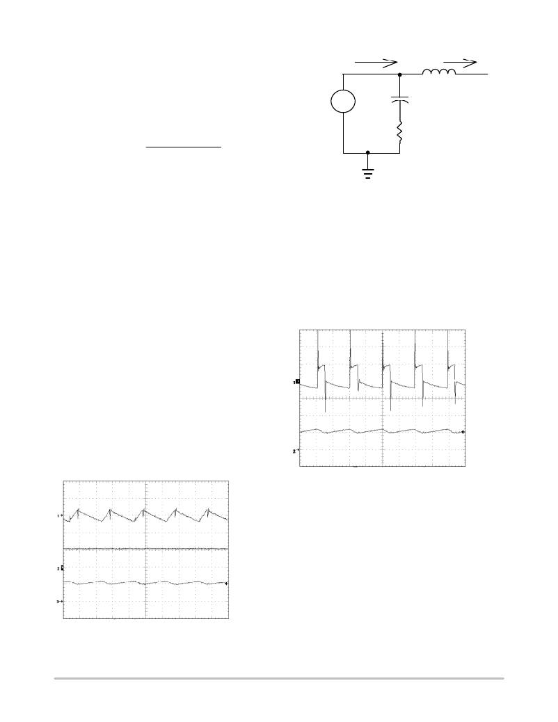
�Input� Capacitor� Selection�
�In� boost� circuits,� the� inductor� becomes� part� of� the� input�
�filter,� as� shown� in� Figure� 35.� In� continuous� mode,� the� input�
�current� waveform� is� triangular� and� does� not� contain� a� large�
�pulsed� current,� as� shown� in� Figure� 34.� This� reduces� the�
�requirements� imposed� on� the� input� capacitor� selection.�
�During� continuous� conduction� mode,� the� peak� to� peak�
�inductor� ripple� current� is� given� in� the� previous� section.� As�
�we� can� see� from� Figure� 34,� the� product� of� the� inductor�
�current� ripple� and� the� input� capacitor� ’s� effective� series�
�resistance� (ESR)� determine� the� V� CC� ripple.� In� most�
�applications,� input� capacitors� in� the� range� of� 10� m� F� to� 100� m� F�
�with� an� ESR� less� than� 0.3� W� work� well� up� to� a� full� 1.5� A�
�switch� current.�
�V� CC� ripple�
�I� IN�
�I� L�
�Figure� 34.� Boost� Input� Voltage� and� Current�
�Figure� 35.� Boost� Circuit� Effective� Input� Filter�
�The� situation� is� different� in� a� flyback� circuit.� The� input�
�current� is� discontinuous� and� a� significant� pulsed� current� is�
�seen� by� the� input� capacitors.� Therefore,� there� are� two�
�requirements� for� capacitors� in� a� flyback� regulator:� energy�
�storage� and� filtering.� To� maintain� a� stable� voltage� supply� to�
�the� chip,� a� storage� capacitor� larger� than� 20� m� F� with� low� ESR�
�is� required.� To� reduce� the� noise� generated� by� the� inductor,�
�insert� a� 1.0� m� F� ceramic� capacitor� between� V� CC� and� ground�
�as� close� as� possible� to� the� chip.�
�Output� Capacitor� Selection�
�V� OUT� ripple�
�I� L�
�Figure� 36.� Typical� Output� Voltage� Ripple�
�By� examining� the� waveforms� shown� in� Figure� 36,� we� can�
�see� that� the� output� voltage� ripple� comes� from� two� major�
�sources,� namely� capacitor� ESR� and� the�
�charging/discharging� of� the� output� capacitor.� In� boost�
�circuits,� when� the� power� switch� turns� off,� I� L� flows� into� the�
�output� capacitor� causing� an� instant� D� V� =� I� IN� � ESR.� At� the�
�same� time,� current� I� L� ?� I� OUT� charges� the� capacitor� and�
�increases� the� output� voltage� gradually.� When� the� power�
�switch� is� turned� on,� I� L� is� shunted� to� ground� and� I� OUT�
�discharges� the� output� capacitor.� When� the� I� L� ripple� is� small�
�enough,� I� L� can� be� treated� as� a� constant� and� is� equal� to� input�
�current� I� IN� .�
�Ripple� Waveforms�
�http://onsemi.com�
�13�
�相关PDF资料 |
PDF描述 |
|---|---|
| HK100568NJ-T | INDUCTOR HI FREQ 68NH 5% 0402 |
| F930G477MNC | CAP TANT 470UF 4V 20% 2917 |
| ASPI-0630HI-1R0M-T15 | INDUCTOR POWER 1.0UH 0630 SMD |
| HK10055N1S-T | INDUCTOR HIFREQ 5.1+/-0.3NH 0402 |
| ISL8204MEVAL1Z | EVAL BOARD 1 FOR ISL8204 |
相关代理商/技术参数 |
参数描述 |
|---|---|
| CS5171ED8 | 功能描述:直流/直流开关调节器 1.5A High Efficiency RoHS:否 制造商:International Rectifier 最大输入电压:21 V 开关频率:1.5 MHz 输出电压:0.5 V to 0.86 V 输出电流:4 A 输出端数量: 最大工作温度: 安装风格:SMD/SMT 封装 / 箱体:PQFN 4 x 5 |
| CS5171ED8G | 功能描述:直流/直流开关调节器 1.5A High Efficiency Boost RoHS:否 制造商:International Rectifier 最大输入电压:21 V 开关频率:1.5 MHz 输出电压:0.5 V to 0.86 V 输出电流:4 A 输出端数量: 最大工作温度: 安装风格:SMD/SMT 封装 / 箱体:PQFN 4 x 5 |
| CS5171EDR8 | 功能描述:直流/直流开关调节器 1.5A High Efficiency RoHS:否 制造商:International Rectifier 最大输入电压:21 V 开关频率:1.5 MHz 输出电压:0.5 V to 0.86 V 输出电流:4 A 输出端数量: 最大工作温度: 安装风格:SMD/SMT 封装 / 箱体:PQFN 4 x 5 |
| CS5171EDR8G | 功能描述:直流/直流开关调节器 1.5A High Efficiency Boost RoHS:否 制造商:International Rectifier 最大输入电压:21 V 开关频率:1.5 MHz 输出电压:0.5 V to 0.86 V 输出电流:4 A 输出端数量: 最大工作温度: 安装风格:SMD/SMT 封装 / 箱体:PQFN 4 x 5 |
| CS5171GD8 | 功能描述:直流/直流开关调节器 1.5A High Efficiency RoHS:否 制造商:International Rectifier 最大输入电压:21 V 开关频率:1.5 MHz 输出电压:0.5 V to 0.86 V 输出电流:4 A 输出端数量: 最大工作温度: 安装风格:SMD/SMT 封装 / 箱体:PQFN 4 x 5 |
发布紧急采购,3分钟左右您将得到回复。