- 您现在的位置:买卖IC网 > PDF目录13377 > CS5171EDR8 (ON Semiconductor)IC REG MULTI CONFIG 1.5A 8SOIC PDF资料下载
参数资料
| 型号: | CS5171EDR8 |
| 厂商: | ON Semiconductor |
| 文件页数: | 10/21页 |
| 文件大小: | 0K |
| 描述: | IC REG MULTI CONFIG 1.5A 8SOIC |
| 产品变化通告: | Product Discontinuation 27/Jun/2007 |
| 标准包装: | 1 |
| 类型: | 升压(升压),回扫,正向转换器,Sepic |
| 输出数: | 1 |
| 输入电压: | 2.7 V ~ 30 V |
| PWM 型: | 电流模式 |
| 频率 - 开关: | 280kHz |
| 电流 - 输出: | 1.5A |
| 同步整流器: | 无 |
| 工作温度: | -40°C ~ 85°C |
| 安装类型: | 表面贴装 |
| 封装/外壳: | 8-SOIC(0.154",3.90mm 宽) |
| 包装: | 剪切带 (CT) |
| 供应商设备封装: | 8-SOICN |
| 其它名称: | CS5171EDR8OSCT |
�� �
�
�CS5171,� CS5172,� CS5173,� CS5174�
�APPLICATIONS� INFORMATION�
�THEORY� OF� OPERATION�
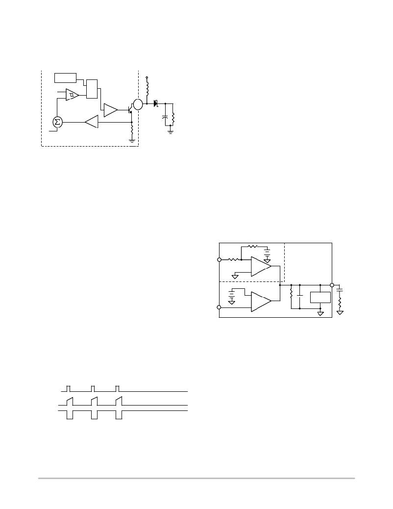
�Current� Mode� Control�
�The� oscillator� is� trimmed� to� guarantee� an� 18%� frequency�
�accuracy.� The� output� of� the� oscillator� turns� on� the� power�
�switch� at� a� frequency� of� 280� kHz� (CS5171/2)� or� 560� kHz�
�V� C�
�Oscillator�
�?�
�+�
�PWM�
�Comparator�
�SUMMER�
�Slope� Compensation�
�S�
�R�
�Q�
�X5�
�Power� Switch�
�In� Out�
�Driver�
�63� m� W�
�V� SW�
�V� CC�
�L�
�D1�
�C� O�
�R� LOAD�
�(CS5173/4),� as� shown� in� Figure� 27.� The� power� switch� is�
�turned� off� by� the� output� of� the� PWM� Comparator.�
�A� TTL� ?� compatible� sync� input� at� the� SS� pin� is� capable� of�
�syncing� up� to� 1.8� times� the� base� oscillator� frequency.� As�
�shown� in� Figure� 28,� in� order� to� sync� to� a� higher� frequency,�
�a� positive� transition� turns� on� the� power� switch� before� the�
�output� of� the� oscillator� goes� high,� thereby� resetting� the�
�oscillator.� The� sync� operation� allows� multiple� power�
�supplies� to� operate� at� the� same� frequency.�
�A� sustained� logic� low� at� the� SS� pin� will� shut� down� the� IC�
�Figure� 27.� Current� Mode� Control� Scheme�
�The� CS517x� family� incorporates� a� current� mode� control�
�scheme,� in� which� the� PWM� ramp� signal� is� derived� from� the�
�power� switch� current.� This� ramp� signal� is� compared� to� the�
�output� of� the� error� amplifier� to� control� the� on� ?� time� of� the�
�power� switch.� The� oscillator� is� used� as� a� fixed� ?� frequency�
�clock� to� ensure� a� constant� operational� frequency.� The�
�resulting� control� scheme� features� several� advantages� over�
�conventional� voltage� mode� control.� First,� derived� directly�
�from� the� inductor,� the� ramp� signal� responds� immediately� to�
�line� voltage� changes.� This� eliminates� the� delay� caused� by� the�
�output� filter� and� error� amplifier,� which� is� commonly� found�
�and� reduce� the� supply� current.�
�An� additional� feature� includes� frequency� shift� to� 20%� of�
�the� nominal� frequency� when� either� the� NFB� or� FB� pins�
�trigger� the� threshold.� During� power� up,� overload,� or� short�
�circuit� conditions,� the� minimum� switch� on� ?� time� is� limited�
�by� the� PWM� comparator� minimum� pulse� width.� Extra�
�switch� off� ?� time� reduces� the� minimum� duty� cycle� to� protect�
�external� components� and� the� IC� itself.�
�As� previously� mentioned,� this� block� also� produces� a� ramp�
�for� the� slope� compensation� to� improve� regulator� stability.�
�Error� Amplifier�
�2.0� V�
�?�
�Voltage�
�1.276� V� +�
�?�
�positive� error� ?� amp�
�in� voltage� mode� controllers.� The� second� benefit� comes� from�
�inherent� pulse� ?� by� ?� pulse� current� limiting� by� merely�
�clamping� the� peak� switching� current.� Finally,� since� current�
�mode� commands� an� output� current� rather� than� voltage,� the�
�filter� offers� only� a� single� pole� to� the� feedback� loop.� This�
�allows� both� a� simpler� compensation� and� a� higher�
�gain� ?� bandwidth� over� a� comparable� voltage� mode� circuit.�
�Without� discrediting� its� apparent� merits,� current� mode�
�control� comes� with� its� own� peculiar� problems,� mainly,�
�subharmonic� oscillation� at� duty� cycles� over� 50%.� The�
�CS517x� family� solves� this� problem� by� adopting� a� slope�
�200� k�
�250� k�
�NFB� +�
�CS5172/4�
�negative� error� ?� amp�
�120� pF�
�1M� W�
�Clamp�
�FB�
�CS5171/3�
�Figure� 29.� Error� Amplifier� Equivalent� Circuit�
�V� C�
�C1�
�0.01� m� F�
�R1�
�5� k� W�
�compensation� scheme� in� which� a� fixed� ramp� generated� by�
�the� oscillator� is� added� to� the� current� ramp.� A� proper� slope�
�rate� is� provided� to� improve� circuit� stability� without�
�sacrificing� the� advantages� of� current� mode� control.�
�Oscillator� and� Shutdown�
�Sync�
�Current�
�Ramp�
�V� SW�
�Figure� 28.� Timing� Diagram� of� Sync� and� Shutdown�
�For� CS5172/4,� the� NFB� pin� is� internally� referenced� to�
�?� 2.5� V� with� approximately� a� 250� k� W� input� impedance.� For�
�CS5171/3,� the� FB� pin� is� directly� connected� to� the� inverting�
�input� of� the� positive� error� amplifier,� whose� non� ?� inverting�
�input� is� fed� by� the� 1.276� V� reference.� Both� amplifiers� are�
�transconductance� amplifiers� with� a� high� output� impedance�
�of� approximately� 1� M� W� ,� as� shown� in� Figure� 29.� The� V� C� pin�
�is� connected� to� the� output� of� the� error� amplifiers� and� is�
�internally� clamped� between� 0.5� V� and� 1.7� V.� A� typical�
�connection� at� the� V� C� pin� includes� a� capacitor� in� series� with�
�a� resistor� to� ground,� forming� a� pole/zero� for� loop�
�compensation.�
�An� external� shunt� can� be� connected� between� the� V� C� pin�
�and� ground� to� reduce� its� clamp� voltage.� Consequently,� the�
�current� limit� of� the� internal� power� transistor� current� is�
�reduced� from� its� nominal� value.�
�http://onsemi.com�
�10�
�相关PDF资料 |
PDF描述 |
|---|---|
| VI-20T-EX-F1 | CONVERTER MOD DC/DC 6.5V 75W |
| VE-J6K-EY-F1 | CONVERTER MOD DC/DC 40V 50W |
| RSC20DRTN-S734 | CONN EDGECARD 40POS DIP .100 SLD |
| VI-20L-EX-F1 | CONVERTER MOD DC/DC 28V 75W |
| VE-J6J-EY-F2 | CONVERTER MOD DC/DC 36V 50W |
相关代理商/技术参数 |
参数描述 |
|---|---|
| CS5171EDR8G | 功能描述:直流/直流开关调节器 1.5A High Efficiency Boost RoHS:否 制造商:International Rectifier 最大输入电压:21 V 开关频率:1.5 MHz 输出电压:0.5 V to 0.86 V 输出电流:4 A 输出端数量: 最大工作温度: 安装风格:SMD/SMT 封装 / 箱体:PQFN 4 x 5 |
| CS5171GD8 | 功能描述:直流/直流开关调节器 1.5A High Efficiency RoHS:否 制造商:International Rectifier 最大输入电压:21 V 开关频率:1.5 MHz 输出电压:0.5 V to 0.86 V 输出电流:4 A 输出端数量: 最大工作温度: 安装风格:SMD/SMT 封装 / 箱体:PQFN 4 x 5 |
| CS5171GD8G | 功能描述:直流/直流开关调节器 1.5A High Efficiency Boost RoHS:否 制造商:International Rectifier 最大输入电压:21 V 开关频率:1.5 MHz 输出电压:0.5 V to 0.86 V 输出电流:4 A 输出端数量: 最大工作温度: 安装风格:SMD/SMT 封装 / 箱体:PQFN 4 x 5 |
| CS5171GDR8 | 功能描述:直流/直流开关调节器 1.5A High Efficiency RoHS:否 制造商:International Rectifier 最大输入电压:21 V 开关频率:1.5 MHz 输出电压:0.5 V to 0.86 V 输出电流:4 A 输出端数量: 最大工作温度: 安装风格:SMD/SMT 封装 / 箱体:PQFN 4 x 5 |
| CS5171GDR8G | 功能描述:直流/直流开关调节器 1.5A High Efficiency Boost RoHS:否 制造商:International Rectifier 最大输入电压:21 V 开关频率:1.5 MHz 输出电压:0.5 V to 0.86 V 输出电流:4 A 输出端数量: 最大工作温度: 安装风格:SMD/SMT 封装 / 箱体:PQFN 4 x 5 |
发布紧急采购,3分钟左右您将得到回复。