- 您现在的位置:买卖IC网 > PDF目录223611 > CS52845ED14 (ON SEMICONDUCTOR) 1 A SWITCHING CONTROLLER, PDSO14 PDF资料下载
参数资料
| 型号: | CS52845ED14 |
| 厂商: | ON SEMICONDUCTOR |
| 元件分类: | 稳压器 |
| 英文描述: | 1 A SWITCHING CONTROLLER, PDSO14 |
| 封装: | 0.150 INCH, MS-012, SO-14 |
| 文件页数: | 1/8页 |
| 文件大小: | 55K |
| 代理商: | CS52845ED14 |
1
Features
s
Optimized for Off-line
Control
s
Temperature
Compensated Oscillator
s
50% Maximum Duty-cycle
Clamp
s
VREF Stabilized before
Output Stage is Enabled
s
Low Start-up Current
s
Pulse-by-pulse Current
Limiting
s
Improved Undervoltage
Lockout
s
Double Pulse Suppression
s
1% Trimmed Bandgap
Reference
s
High Current Totem Pole
Output
Package Options
CS52845
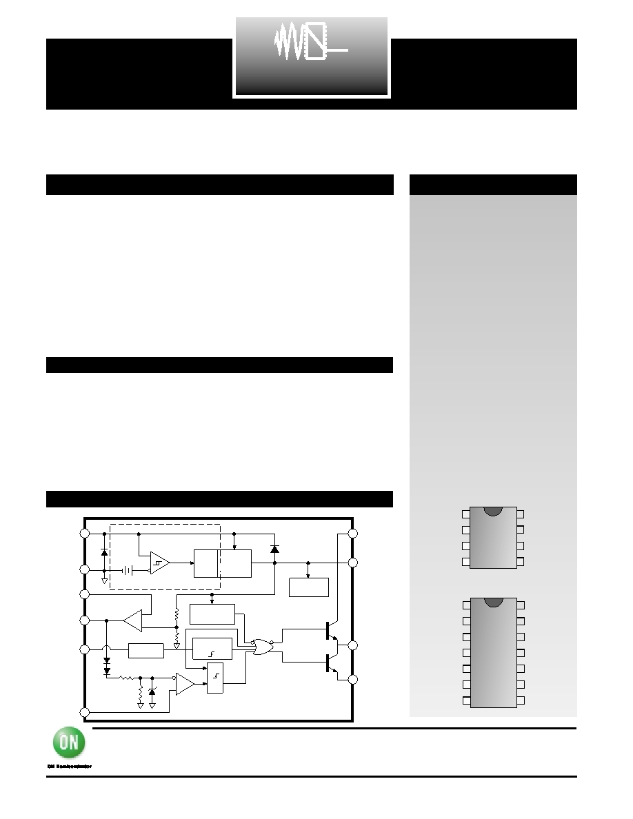
Current Mode PWM Control Circuit
with 50% Max Duty Cycle
CS52845
Description
Block Diagram
Absolute Maximum Ratings
10
7
14
13
12
8
1
2
3
4
5
6
11
9
COMP
NC
VFB
NC
Sense
NC
OSC
VREF
NC
VCC
VCC Pwr
VOUT
Pwr Gnd
Gnd
14L SO Narrow
1
7
8
2
3
4
5
6
COMP
VFB
Sense
OSC
VREF
VCC
VOUT
Gnd
8L SO Narrow
December, 2001 - Rev. 3
ON Semiconductor
2000 South County Trail, East Greenwich, RI 02818
Tel: (401)885–3600 Fax: (401)885–5786
N. American Technical Support: 800-282-9855
Web Site: www.cherry–semi.com
ARCHIVE
DEVICE
NOT
RECOMMENDED
FOR
NEW
DESIGN
The CS52845 provides all the nec-
essary features to implement off-
line fixed frequency current-mode
control with a minimum number
of external components.
The CS52845 incorporates a new
precision temperature-controlled
oscillator to minimize variations in
frequency. An internal toggle flip-
flop, which blanks the output
every other clock cycle, limits the
duty-cycle range to less than 50%.
An undervoltage lockout ensures
that VREF is stabilized before the
output stage is enabled. In the
CS52845 turn on is at 8.4V and
turn off at 7.6V.
Other features include low start-up
current, pulse-by-pulse current lim-
iting, and a high-current totem pole
output for driving capacitive loads,
such as gate of a power MOSFET.
The output is low in the off state,
consistent with N-channel devices.
Supply Voltage (ICC<30mA) ..........................................................Self Limiting
Supply Voltage (Low Impedance Source)...................................................30V
Output Current ...............................................................................................±1A
Output Energy (Capacitive Load) .................................................................5J
Analog Inputs (VFB, VSENSE)...........................................................-0.3V to 5.5V
Error Amp Output Sink Current...............................................................10mA
Lead Temperature Soldering
Reflow (SMD styles only) ...........60 sec. max above 183°C, 230°C peak
VCC
Gnd
COMP
OSC
Sense
VREF
Undervoltage
Lockout
Internal
Bias
NOR
S
R
PWM
Latch
Current
Sensing
Comparator
R
2 R
1V
Error
Amplifier
-
+
2.50V
Set/
Reset
VCC Undervoltage Lock-out
34V
8.4V/7.6V
R
VFB
VCC Pwr
VOUT
Pwr Gnd
Oscillator
Toggle
Flip-Flop
5.0 Volt
Reference
相关PDF资料 |
PDF描述 |
|---|---|
| CS8442XN8 | STEPPER MOTOR CONTROLLER, PDIP8 |
| CS9ARH-FREQ1 | CRYSTAL OSCILLATOR, CLOCK, 50 MHz - 300 MHz, PECL OUTPUT |
| CS9TRH-FREQ2 | CRYSTAL OSCILLATOR, CLOCK, 300.001 MHz - 700 MHz, PECL OUTPUT |
| CS9ASH-FREQ1 | CRYSTAL OSCILLATOR, CLOCK, 50 MHz - 300 MHz, PECL OUTPUT |
| CS9AUH-FREQ1 | CRYSTAL OSCILLATOR, CLOCK, 50 MHz - 300 MHz, PECL OUTPUT |
相关代理商/技术参数 |
参数描述 |
|---|---|
| CS52845ED8 | 制造商:CHERRY 制造商全称:CHERRY 功能描述:Current Mode PWM Control Circuit with 50% Max Duty Cycle |
| CS52845EDR14 | 制造商:CHERRY 制造商全称:CHERRY 功能描述:Current Mode PWM Control Circuit with 50% Max Duty Cycle |
| CS52845EDR8 | 制造商:Rochester Electronics LLC 功能描述:- Bulk 制造商:ON Semiconductor 功能描述: |
| CS5293BT | 制造商:Rochester Electronics LLC 功能描述:- Bulk 制造商:Cypress Semiconductor 功能描述: |
| CS52A | 制造商:Aten International 功能描述: |
发布紧急采购,3分钟左右您将得到回复。