- 您现在的位置:买卖IC网 > PDF目录295335 > CS5332GDW28 (ON SEMICONDUCTOR) 1.5 A SWITCHING CONTROLLER, 1000 kHz SWITCHING FREQ-MAX, PDSO28 PDF资料下载
参数资料
| 型号: | CS5332GDW28 |
| 厂商: | ON SEMICONDUCTOR |
| 元件分类: | 稳压器 |
| 英文描述: | 1.5 A SWITCHING CONTROLLER, 1000 kHz SWITCHING FREQ-MAX, PDSO28 |
| 封装: | SOP-28 |
| 文件页数: | 5/20页 |
| 文件大小: | 400K |
| 代理商: | CS5332GDW28 |
CS5332
http://onsemi.com
13
Ramp Size and Current Sensing
Because the current ramp is used for both the PWM ramp
and to sense current, the inductor and sense resistor values
will be constrained. A small ramp will provide a quick
transient response by minimizing the difference over which
the COMP pin must travel between light and heavy loads,
but a steady state ramp of 25 mVPP or greater is typically
required to prevent pulse skipping and minimize pulse width
jitter. For resistive current sensing, the combination of the
inductor and sense resistor values must be chosen to provide
a large enough steady state ramp. For large inductor values
the sense resistor value must also be increased.
For inductive current sensing the RC network must meet
the requirement of L/RL = R × C to accurately sense the AC
and DC components of the current the signal. Again the
values for L and RL will be constrained in order to provide
a large enough steady state ramp with a compensated current
sense signal. A smaller L, or a larger RL than optimum might
be required. But unlike resistive sensing, with inductive
sensing small adjustments can be made easily with the
values of R and C to increase the ramp size if needed.
If RC is chosen to be smaller (faster) than L/RL, the AC
portion of the current sensing signal will be scaled larger
than the DC portion. This will provide a larger steady state
ramp, but circuit performance will be affected and must be
evaluated carefully. The current signal will overshoot during
transients and settle at the rate determined by R × C. It will
eventually settle to the correct DC level, but the error will
decay with the time constant of R × C. If this error is
excessive it will effect transient response, adaptive
positioning and current limit. During transients, the COMP
pin will be required to overshoot along with the current
signal in order to maintain the output voltage. The VDRP pin
will also overshoot during transients and possibly slow the
response. Single phase overcurrent will trip earlier than it
would if compensated correctly and hiccup mode current
limit will have a lower threshold for fast rise step loads than
for slowly rising output currents.
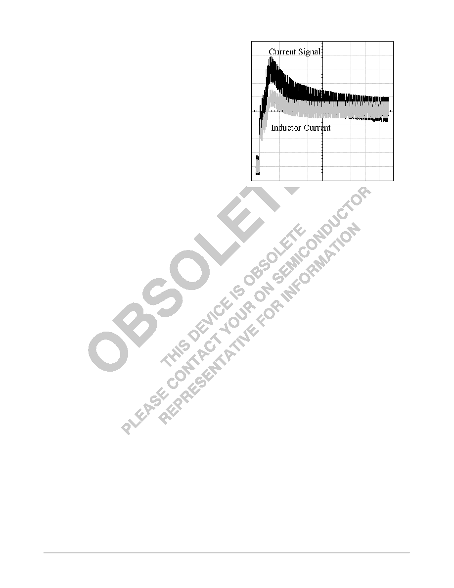
The waveforms in Figure 13 show a simulation of the
current sense signal and the actual inductor current during
a positive step in load current with values of L = 500 nH,
RL = 1.6 mΩ, R1 = 20 k and C1 = .01 μF. For ideal current
signal compensation the value of R1 should be 31 kΩ. Due
to the faster than ideal RC time constant there is an
overshoot of 50% and the overshoot decays with a 200 μs
time constant. With this compensation the ILIM pin
threshold must be set more than 50% above the full load
current to avoid triggering hiccup mode during a large
output load step.
Figure 13. Inductive Sensing waveform during a
Load Step with Fast RC Time Constant (50 μs/div)
Current Limit
Two levels of overcurrent protection are provided. Any
time the voltage on a Current Sense pin exceeds CSREF by
more than the Single Phase Pulse by Pulse Current Limit, the
PWM comparator for that phase is turned off. This provides
fast peak current protection for individual phases. The
outputs of all the currents are also summed and filtered to
compare an averaged current signal to the voltage on the
ILIM pin. If this voltage is exceeded, the fault latch trips and
the Soft Start capacitor is discharged by a 7.5 μA source until
the COMP pin reaches 0.2 V. Then SoftStart begins. The
converter will continue to operate in this mode until the fault
condition is corrected.
Overvoltage Protection
Overvoltage protection (OVP) is provided as a result of
the normal operation of the Enhanced V2 control topology
with synchronous rectifiers. The control loop responds to an
overvoltage condition within 400 ns, causing the top
MOSFET’s to shut off, and the synchronous MOSFET’s to
turn on. This results in a “crowbar” action to clamp the
output voltage and prevent damage to the load. The regulator
will remain in this state until the overvoltage condition
ceases or the input voltage is pulled low.
Transient Response and Adaptive Positioning
For applications with fast transient currents the output
filter is frequently sized larger than ripple currents require in
相关PDF资料 |
PDF描述 |
|---|---|
| CS600/L2 | 1 CHANNEL LOGIC OUTPUT OPTOCOUPLER |
| CSBLA384KECE-B0 | CERAMIC RESONATOR, 0.384 MHz |
| CSC5026-0102F | 16 CONTACT(S), COMBINATION LINE CONNECTOR, SOCKET |
| CSD10030 | ZERO RECOVERY RECTIFIER |
| CSD10030A | ZERO RECOVERY RECTIFIER |
相关代理商/技术参数 |
参数描述 |
|---|---|
| CS5332GDWR28 | 功能描述:IC REG CTRLR BUCK PWM 28-SOIC RoHS:否 类别:集成电路 (IC) >> PMIC - 稳压器 - DC DC 切换控制器 系列:- 标准包装:4,000 系列:- PWM 型:电压模式 输出数:1 频率 - 最大:1.5MHz 占空比:66.7% 电源电压:4.75 V ~ 5.25 V 降压:是 升压:无 回扫:无 反相:无 倍增器:无 除法器:无 Cuk:无 隔离:无 工作温度:-40°C ~ 85°C 封装/外壳:40-VFQFN 裸露焊盘 包装:带卷 (TR) |
| CS5333 | 制造商:CIRRUS 制造商全称:Cirrus Logic 功能描述:24-Bit, 96 kHz Stereo A/D Converter |
| CS5333-BZ | 制造商:Rochester Electronics LLC 功能描述:- Bulk |
| CS5333-KZ | 制造商:CIRRUS 制造商全称:Cirrus Logic 功能描述:24-Bit, 96 kHz Stereo A/D Converter |
| CS5333-KZR | 制造商:Cirrus Logic 功能描述: |
发布紧急采购,3分钟左右您将得到回复。