参数资料
| 型号: | CS5364-CQZR |
| 厂商: | Cirrus Logic Inc |
| 文件页数: | 24/42页 |
| 文件大小: | 0K |
| 描述: | IC ADC 4CH 114DB 216KHZ 48-LQFP |
| 标准包装: | 2,000 |
| 位数: | 24 |
| 采样率(每秒): | 216k |
| 数据接口: | 串行 |
| 转换器数目: | 1 |
| 功率耗散(最大): | 580mW |
| 电压电源: | 模拟和数字 |
| 工作温度: | -40°C ~ 85°C |
| 安装类型: | 表面贴装 |
| 封装/外壳: | 48-LQFP |
| 供应商设备封装: | 48-LQFP(7x7) |
| 包装: | 带卷 (TR) |
| 输入数目和类型: | 4 个差分,单极 |
| 配用: | CDB5364-ND - EVALUATION BOARD FOR CS5364 |
第1页第2页第3页第4页第5页第6页第7页第8页第9页第10页第11页第12页第13页第14页第15页第16页第17页第18页第19页第20页第21页第22页第23页当前第24页第25页第26页第27页第28页第29页第30页第31页第32页第33页第34页第35页第36页第37页第38页第39页第40页第41页第42页
30
DS625F4
CS5364
4.13
Control Port Operation
The Control Port is used to read and write the internal device registers. It supports two industry standard
formats, IC and SPI. The part is in IC format by default. SPI Mode is selected if there is ever a high-to-low
transition on the AD0/CS pin after the RST pin has been restored high.
In Control Port Mode, all features of the CS5364 are available. Four multi-use configuration pins become
software pins that support the IC or SPI bus protocol. To initiate Control Port Mode, a controller that sup-
ports IC or SPI must be used to enable the internal register functionality. This is done by setting the
CP-EN bit (Bit 7 of the Global Control Port Register). Once CP-EN is set, all of the device configuration pins
are ignored, and the internal register settings determine the operating modes of the part.
4.13.1
SPI Mode
In SPI Mode, CS is the CS5364 chip select signal; CCLK is the control port bit clock (input into the CS5364
from a controller); CDIN is the input data line from a controller; CDOUT is the output data line to a controller.
Data is clocked in on the rising edge of CCLK and is supplied on the falling edge of CCLK.
To write to a register, bring CS low. The first seven bits on CDIN form the chip address and must be
1001111. The eighth bit is a read/write indicator (R/W), which should be low to write. The next eight bits
form the Memory Address Pointer (MAP), which is set to the address of the register that is to be updated.
The next eight bits are the data that will be placed into the register designated by the MAP. During writes,
the CDOUT output stays in the Hi-Z state. It may be externally pulled high or low with a 47 k
Ω resistor, if
desired.
There is a MAP auto-increment capability, which is enabled by the INCR bit in the MAP register. If INCR is
a zero, the MAP will stay constant for successive read or writes. If INCR is set to a 1, the MAP will auto-
increment after each byte is read or written, allowing block reads or writes of successive registers.
To read a register, the MAP has to be set to the correct address by executing a partial write cycle that fin-
ishes (CS high) immediately after the MAP byte. The MAP auto-increment bit (INCR) may be set or not, as
desired. To begin a read, bring CS low, send out the chip address and set the read/write bit (R/W) high.
The next falling edge of CCLK will clock out the MSB of the addressed register (CDOUT will leave the high
impedance state). If the MAP auto-increment bit is set to 1, the data for successive registers will appear
consecutively
.
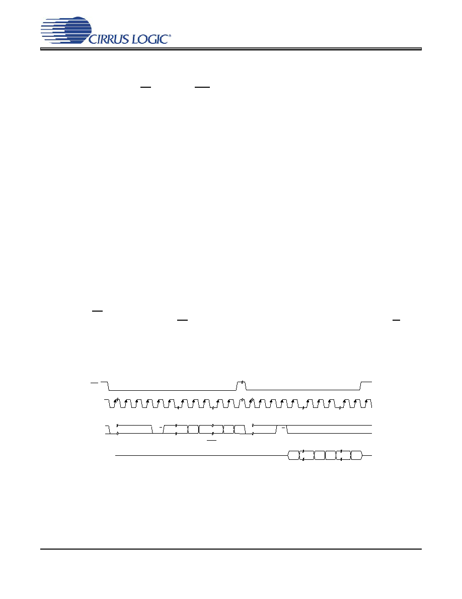
Figure 16. SPI Format
MA P
MSB
LSB
DATA
by te 1
by te n
R/W
AD D R ESS
CH IP
ADDRESS
CH I P
CD I N
CC L K
CS
CD O U T
MSB
LSB MSB
LSB
1001111
MAP = Memory Address Pointer, 8 bits, MSB first
High Impedance
相关PDF资料 |
PDF描述 |
|---|---|
| CS5366-DQZR | IC ADC 6CH 114DB 216KHZ 48-LQFP |
| CS5368-DQZ | IC ADC 8CH 114DB 216KHZ 48-LQFP |
| CS5381-KSZ | IC ADC AUD 120DB 192KHZ 24-SOIC |
| CS53L21-CNZR | IC ADC STEREO 24BIT 98DB 32-QFN |
| CS5509-ASZR | IC ADC 16BIT SGL SUPP 16-SOIC |
相关代理商/技术参数 |
参数描述 |
|---|---|
| CS5364-DQZ | 功能描述:音频模/数转换器 IC 114dB 192kHz 4-Ch ADC w/TDM Interface RoHS:否 制造商:Wolfson Microelectronics 转换速率: 分辨率: ADC 输入端数量: 工作电源电压: 最大工作温度: 最小工作温度: 安装风格: 封装 / 箱体: 封装: |
| CS5364-DQZR | 功能描述:音频模/数转换器 IC IC 114dB 192kHz 4ch ADC w/TDM Intrfc RoHS:否 制造商:Wolfson Microelectronics 转换速率: 分辨率: ADC 输入端数量: 工作电源电压: 最大工作温度: 最小工作温度: 安装风格: 封装 / 箱体: 封装: |
| CS5366 | 制造商:CIRRUS 制造商全称:Cirrus Logic 功能描述:114 dB, 192 kHz, 6-Channel A/D Converter |
| CS5366_08 | 制造商:CIRRUS 制造商全称:Cirrus Logic 功能描述:114 dB, 192 kHz, 6-Channel A/D Converter |
| CS5366_09 | 制造商:CIRRUS 制造商全称:Cirrus Logic 功能描述:114 dB, 192 kHz, 6-Channel A/D Converter |
发布紧急采购,3分钟左右您将得到回复。