- 您现在的位置:买卖IC网 > PDF目录11818 > CS82C50A-5Z (Intersil)IC COMMUNICATION ELEMENT 44-PLCC PDF资料下载
参数资料
| 型号: | CS82C50A-5Z |
| 厂商: | Intersil |
| 文件页数: | 2/25页 |
| 文件大小: | 0K |
| 描述: | IC COMMUNICATION ELEMENT 44-PLCC |
| 标准包装: | 26 |
| 特点: | 单芯片 UART/BRG |
| 通道数: | 1,UART |
| 规程: | RS232C |
| 电源电压: | 4.5 V ~ 5.5 V |
| 带并行端口: | 是 |
| 带故障启动位检测功能: | 是 |
| 带调制解调器控制功能: | 是 |
| 带CMOS: | 是 |
| 安装类型: | 表面贴装 |
| 封装/外壳: | 44-LCC(J 形引线) |
| 供应商设备封装: | 44-PLCC |
| 包装: | 管件 |
| 产品目录页面: | 1242 (CN2011-ZH PDF) |
10
FN2958.5
August 24, 2006
82C50A
MCR(3): When MCR(3) is set high, the OUT2 output is
forced low. When MCR(3) is reset low, the OUT2 output is
forced high. OUT2 is an user designated output.
MCR(4): MCR(4) provides a local loopback feature for
diagnostic testing of the 62C50A. When MCR(4) is set high,
Serial Output (SOUT) is set to the marking (logic 1) state,
and the receiver data input Serial Input (SIN) is
disconnected. The output of the Transmitter Shift Register is
looped back into the Receiver Shift Register input. The four
modem control inputs (CTS, DSR, DC, and RI) are
disconnected. The four modem control outputs (DTR, RTS,
OUT1 and OUT2) are internally connected to the four
modem control inputs. The modem control output pins are
forced to their inactive state (high). In the diagnostic mode,
data transmitted is immediately received. This allows the
processor to verify the transmit and receive data paths of the
82C50A.
In the diagnostic mode, the receiver and transmitter
interrupts are fully operational. The modem control interrupts
are also operational, but the interrupt sources are now the
lower four bits of the MCR instead of the four modem control
inputs. The interrupts are still controlled by the Interrupt
Enable Register.
MCR(5) - MCR(7): These bits are permanently set to logic 0.
MODEM STATUS REGISTER (MSR)
The MSR provides the CPU with status of the modem input
lines from the modem or peripheral device. The MSR allows
the CPU to read the modem signal inputs by accessing the
data bus interface of the 82C50A. In addition to the current
status information, four bits of the MSR indicate whether the
modem inputs have changed since the last reading of the
MSR. The delta status bits are set high when a control input
from the modem changes state, and reset low when the
CPU reads the MSR.
The modem input lines are CTS (pin 36), DSR (pin 37), RI
(pin 39), and DCD (pin 38). MSR(4) - MSR(7) are status
indications of these lines. The status indications follow the
status of the input lines. If the modem status interrupt in the
Interrupt Enable Register is enabled (IER(3)), a change of
state in a modem input signals will be reflected by the
modem status bits in the lIR register, and an interrupt
(lNTRPT) is generated. The MSR is a priority 4 interrupt. The
contents of the Modem Status Register are described below:
Note that the state (high or low) of the status bits are
inverted versions of the actual input pins.
MSR(0) Delta Clear to Send (DCTS): DCTS indicates that
the CTS input (Pin-36) to the 82C50A has changed state
since the last time it was read by the CPU.
MSR(1) Delta Data Set Ready (DDSR): DDSR indicates
that the DSR input (Pin-37) to the 62C50A has changed
state since the last time it was read by the CPU.
MSR(2) Trailing Edge of Ring Indicator (TERI): TERI
indicates that the RI input (Pin-39) to the 82C50A has
Changed state from Low to High since the last time it was
read by the CPU. High to Low transitions on RI do not
activate TERI.
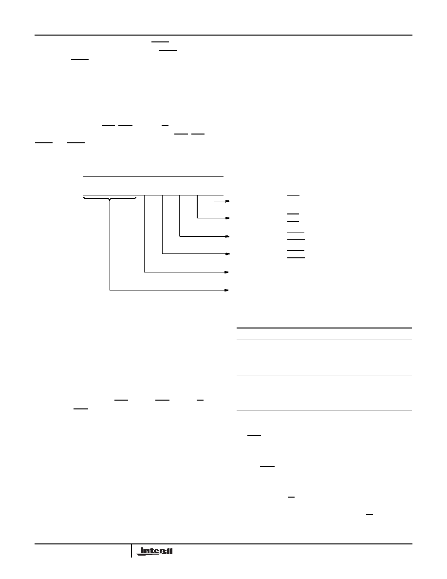
MODEM CONTROL REGISTER (MCR)
MCR
7
MCR
6
MCR
5
MCR
4
MCR
3
MCR
2
MCR
1
MCR
0
Data Terminal
Ready
0 = DTR Output High (Inactive)
1 = DTR Output Low (Active)
Request to
Send
0 = RTS Output High (Inactive)
1 = RTS Output Low (Active)
Out 1
0 = OUT 1 Output High (Inactive)
1 = OUT 1 Output Low (Active)
Out 2
0 = OUT 2 Output High (Inactive)
1 = OUT 2 Output Low (Active)
Loop
0 = Loop Disabled
1 = Loop Enabled
These Bits are Permanently Set to a Logic 0.
MSR BITS 0 THRU 7
MSR BIT
MNEMONIC
DESCRIPTION
MSR (1)
DDSR
Delta Data Set Ready
MSR (2)
TERI
Trailing Edge of Ring Indicator
MSR (0)
DCTS
Delta Clear To Send
MSR (3)
DDCD
Delta Data Carrier Detect
MSR (4)
CTS
Clear To Send
MSR (5)
DSR
Data Set Ready
MSR (6)
RI
Ring Indicator
MSR (7)
DCD
Data Carrier Detect
相关PDF资料 |
PDF描述 |
|---|---|
| CP82C52Z | IC UART/BRG 5V 16MHZ 28-PDIP |
| ATUC128D4-AUR | IC MCU 32BIT 128KB FLASH 48TQFP |
| VI-B72-IW-F2 | CONVERTER MOD DC/DC 15V 100W |
| V24C12H150B2 | CONVERTER MOD DC/DC 12V 150W |
| VI-B71-IX-F3 | CONVERTER MOD DC/DC 12V 75W |
相关代理商/技术参数 |
参数描述 |
|---|---|
| CS82C50A-5Z96 | 功能描述:UART 接口集成电路 W/ANNEAL 44 PLCC 0+7 0C 5 0V 10 0MHZ RoHS:否 制造商:Texas Instruments 通道数量:2 数据速率:3 Mbps 电源电压-最大:3.6 V 电源电压-最小:2.7 V 电源电流:20 mA 最大工作温度:+ 85 C 最小工作温度:- 40 C 封装 / 箱体:LQFP-48 封装:Reel |
| CS82C52 | 制造商:Rochester Electronics LLC 功能描述:- Bulk |
| CS82C5296 | 功能描述:IC UART/BRG 5V 16MHZ 28-PLCC RoHS:否 类别:集成电路 (IC) >> 接口 - UART(通用异步接收器/发送器) 系列:- 标准包装:250 系列:- 特点:* 通道数:2,DUART FIFO's:16 字节 规程:RS232,RS485 电源电压:2.25 V ~ 5.5 V 带并行端口:- 带自动流量控制功能:是 带IrDA 编码器/解码器:是 带故障启动位检测功能:是 带调制解调器控制功能:是 带CMOS:是 安装类型:表面贴装 封装/外壳:48-TQFP 供应商设备封装:48-TQFP(7x7) 包装:托盘 其它名称:XR16L2551IM-F-ND |
| CS82C52Z | 功能描述:UART 接口集成电路 A/ANNEAL PERIPH UART /BRG 5V 16MHZ 28PLCC RoHS:否 制造商:Texas Instruments 通道数量:2 数据速率:3 Mbps 电源电压-最大:3.6 V 电源电压-最小:2.7 V 电源电流:20 mA 最大工作温度:+ 85 C 最小工作温度:- 40 C 封装 / 箱体:LQFP-48 封装:Reel |
| CS82C52Z96 | 功能描述:UART 接口集成电路 A/ANNEAL PERIPH UART /BRG 5V 16MHZ 28PLCC RoHS:否 制造商:Texas Instruments 通道数量:2 数据速率:3 Mbps 电源电压-最大:3.6 V 电源电压-最小:2.7 V 电源电流:20 mA 最大工作温度:+ 85 C 最小工作温度:- 40 C 封装 / 箱体:LQFP-48 封装:Reel |
发布紧急采购,3分钟左右您将得到回复。