- 您现在的位置:买卖IC网 > PDF目录170654 > DAC8554IPW (TEXAS INSTRUMENTS INC) SERIAL INPUT LOADING, 12 us SETTLING TIME, 16-BIT DAC, PDSO16 PDF资料下载
参数资料
| 型号: | DAC8554IPW |
| 厂商: | TEXAS INSTRUMENTS INC |
| 元件分类: | DAC |
| 英文描述: | SERIAL INPUT LOADING, 12 us SETTLING TIME, 16-BIT DAC, PDSO16 |
| 封装: | GREEN, PLASTIC, TSSOP-16 |
| 文件页数: | 8/31页 |
| 文件大小: | 1039K |
| 代理商: | DAC8554IPW |
第1页第2页第3页第4页第5页第6页第7页当前第8页第9页第10页第11页第12页第13页第14页第15页第16页第17页第18页第19页第20页第21页第22页第23页第24页第25页第26页第27页第28页第29页第30页第31页
www.ti.com
SLAS431B – JUNE 2005 – REVISED OCTOBER 2006
The DAC8554 also supports a number of different
Power-down/data selection is as follows:
load
commands.
The
load
commands
include
DB16 is a power-down flag. If this flag is set, then
broadcast commands to address all the DAC8554s
DB15 and DB14 select one of the four power-down
on an SPI bus. The load commands can be
modes of the device as described in Table 1. If DB16
summarized as follows:
= 1, DB15 and DB14 no longer represent the two
DB21 = 0 and DB20 = 0: Single-channel store.
MSBs of data, but represent a power-down condition
The temporary register (data buffer) corresponding to
described in Table 1. Similar to data, power-down
a DAC selected by DB18 and DB17 is updated with
conditions can be stored at the temporary registers
the contents of SR data (or power-down).
of each DAC. It is possible to update DACs
simultaneously either with data, power-down, or a
DB21 = 0 and DB20 = 1: Single-channel update.
combination of both.
The
temporary
register
and
DAC
register
corresponding to a DAC selected by DB18 and DB17
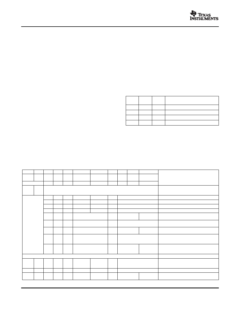
Refer to Table 2 for more information.
are updated with the contents of SR data (or
power-down).
Table 1. DAC8554 Power-Down Modes
PD0
PD1
PD2
DB21 = 1 and DB20 = 0: Simultaneous update. A
(DB16)
(DB15)
(DB14)
OPERATING MODE
channel selected by DB18 and DB17 gets updated
1
0
Output high impedance
with the SR data, and simultaneously, all the other
channels get updated with previous stored data (or
1
0
1
Output typically 1k
to GND
power-down) from temporary registers.
1
0
Output typically 100k
to GND
1
Output high impedance
DB21 = 1 and DB20 = 1: Broadcast update. All the
DAC8554s on the SPI bus respond, regardless of
address matching. If DB18 = 0, then SR data gets
ignored, all channels from all DAC8554s get updated
with previously stored data (or power-down). If DB18
= 1, then SR data (or power-down) updates all
channels of all DAC8554s in the system. This
broadcast update feature allows the simultaneous
update of up to 16 channels.
Table 2. Control Matrix
DB23
DB22
DB21
DB20
DB19
DB18
DB17
DB16
DB15
DB14
DB13-DB0
Don't
A1
A0
LD 1
LD 0
Care
DAC Sel 1
DAC Sel 0
PD0
MSB
MSB-1
MSB-2...LSB
(Address Select)
DESCRIPTION
0/1
This address selects 1 of 4 possible devices on a
single SPI data bus based on each device's address
See Below
pin(s) state.
0
X
0
Data
Write to buffer A with data
0
X
0
1
0
Data
Write to buffer B with data
0
X
1
0
Data
Write to buffer C with data
0
X
1
0
Data
Write to buffer D with data
Write to buffer (selected by DB17 and DB18) with
0
X
(00, 01, 10, or 11)
1
See Table 1
0
power-down command
A0 and A1 should
correspond to the
Write to buffer with data and load DAC (selected by
0
1
X
(00, 01, 10, or 11)
0
Data
package address
DB17 and DB18)
set via pins 13
Write to buffer with power-down command and load
and 14.
0
1
X
(00, 01, 10, or 11)
1
See Table 1
0
DAC (selected by DB17 and DB18)
Write to buffer with data (selected by DB17 and DB18)
1
0
X
(00, 01, 10, or 11)
0
Data
and then load all DACs simultaneously from their
corresponding buffers.
Write to buffer with power-down command (selected by
1
0
X
(00, 01, 10, or 11)
1
See Table 1
0
DB17 and DB18) and then load all DACs
simultaneously from their corresponding buffers.
Broadcast Modes
Simultaneously update all channels of all DAC8554
X
1
X
0
X
devices in the system with data stored in each
channels temporary register.
X
1
X
1
X
0
Data
Write to all devices and load all DACs with SR data
Write to all devices and load all DACs with
X
1
X
1
X
1
See Table 1
0
power-down command in SR.
16
相关PDF资料 |
PDF描述 |
|---|---|
| DAC8564IAPWR | SERIAL INPUT LOADING, 12 us SETTLING TIME, 16-BIT DAC, PDSO16 |
| DAC8564IBPW | SERIAL INPUT LOADING, 12 us SETTLING TIME, 16-BIT DAC, PDSO16 |
| DAC8564ICPWR | SERIAL INPUT LOADING, 12 us SETTLING TIME, 16-BIT DAC, PDSO16 |
| DAC8564IDPW | SERIAL INPUT LOADING, 12 us SETTLING TIME, 16-BIT DAC, PDSO16 |
| DAC8564IAPWG4 | SERIAL INPUT LOADING, 12 us SETTLING TIME, 16-BIT DAC, PDSO16 |
相关代理商/技术参数 |
参数描述 |
|---|---|
| DAC8554IPWG4 | 功能描述:数模转换器- DAC 16-Bit Quad Ch UltLo Glitch Vltg Output RoHS:否 制造商:Texas Instruments 转换器数量:1 DAC 输出端数量:1 转换速率:2 MSPs 分辨率:16 bit 接口类型:QSPI, SPI, Serial (3-Wire, Microwire) 稳定时间:1 us 最大工作温度:+ 85 C 安装风格:SMD/SMT 封装 / 箱体:SOIC-14 封装:Tube |
| DAC8554IPWR | 功能描述:数模转换器- DAC 16-Bit Quad Ch UltLo Glitch Vltg Output RoHS:否 制造商:Texas Instruments 转换器数量:1 DAC 输出端数量:1 转换速率:2 MSPs 分辨率:16 bit 接口类型:QSPI, SPI, Serial (3-Wire, Microwire) 稳定时间:1 us 最大工作温度:+ 85 C 安装风格:SMD/SMT 封装 / 箱体:SOIC-14 封装:Tube |
| DAC8554IPWRG4 | 功能描述:数模转换器- DAC 16-Bit Quad Ch UltLo Glitch Vltg Output RoHS:否 制造商:Texas Instruments 转换器数量:1 DAC 输出端数量:1 转换速率:2 MSPs 分辨率:16 bit 接口类型:QSPI, SPI, Serial (3-Wire, Microwire) 稳定时间:1 us 最大工作温度:+ 85 C 安装风格:SMD/SMT 封装 / 箱体:SOIC-14 封装:Tube |
| DAC8555 | 制造商:BB 制造商全称:BB 功能描述:16-BIT, QUAD CHANNEL, ULTRALOW GLITCH, VOLTAGE OUTPUT DIGITAL-TO-ANALOG CONVERTER |
| DAC8555EVM | 功能描述:数据转换 IC 开发工具 QUAD CH. DAC RoHS:否 制造商:Texas Instruments 产品:Demonstration Kits 类型:ADC 工具用于评估:ADS130E08 接口类型:SPI 工作电源电压:- 6 V to + 6 V |
发布紧急采购,3分钟左右您将得到回复。