- 您现在的位置:买卖IC网 > PDF目录16613 > DC1561B (Linear Technology)EVAL BOARD FOR LTC4278 PDF资料下载
参数资料
| 型号: | DC1561B |
| 厂商: | Linear Technology |
| 文件页数: | 13/42页 |
| 文件大小: | 0K |
| 描述: | EVAL BOARD FOR LTC4278 |
| 标准包装: | 1 |
| 主要目的: | 电源管理,以太网供电(POE) |
| 嵌入式: | 否 |
| 已用 IC / 零件: | LTC4278 |
| 已供物品: | 板 |
第1页第2页第3页第4页第5页第6页第7页第8页第9页第10页第11页第12页当前第13页第14页第15页第16页第17页第18页第19页第20页第21页第22页第23页第24页第25页第26页第27页第28页第29页第30页第31页第32页第33页第34页第35页第36页第37页第38页第39页第40页第41页第42页
LTC4278
20
4278fc
Classification Resistor (RCLASS)
The RCLASS resistor sets the classification load current,
corresponding to the PD power classification. Select the
value of RCLASS from Table 2 and connect the resistor
between the RCLASS and VPORTN pins as shown in Figure
4, or float the RCLASS pin if the classification load cur-
rent is not required. The resistor tolerance must be 1%
or better to avoid degrading the overall accuracy of the
classification circuit.
Load Capacitor
The IEEE 802.3af/at specification requires that the PD
maintains a minimum load capacitance of 5μF and does
not specify a maximum load capacitor. However, if the
load capacitor is too large, there may be a problem with
inadvertent power shutdown by the PSE.
This occurs when the PSE voltage drops quickly. The input
diode bridge reverses bias, and the PD load momentarily
powers off the load capacitor. If the PD does not draw
power within the PSE’s 300ms disconnection delay, the
PSE may remove power from the PD. Thus, it is necessary
to evaluate the load current and capacitance to ensure that
an inadvertent shutdown cannot occur.
The load capacitor can store significant energy when fully
charged. The PD design must ensure that this energy is
not inadvertently dissipated in the LTC4278. For example,
if the VPORTP pin shorts to VPORTN while the capacitor
is charged, current will flow through the parasitic body
diode of the internal MOSFET and may cause permanent
damage to the LTC4278.
T2P Interface
When a 2-event classification sequence successfully
completes, the LTC4278 recognizes this sequence, and
provides an indicator bit, declaring the presence of a
Type 2 PSE. The open-drain output provides the option
to use this signal to communicate to the LTC4278 load,
or to leave the pin unconnected.
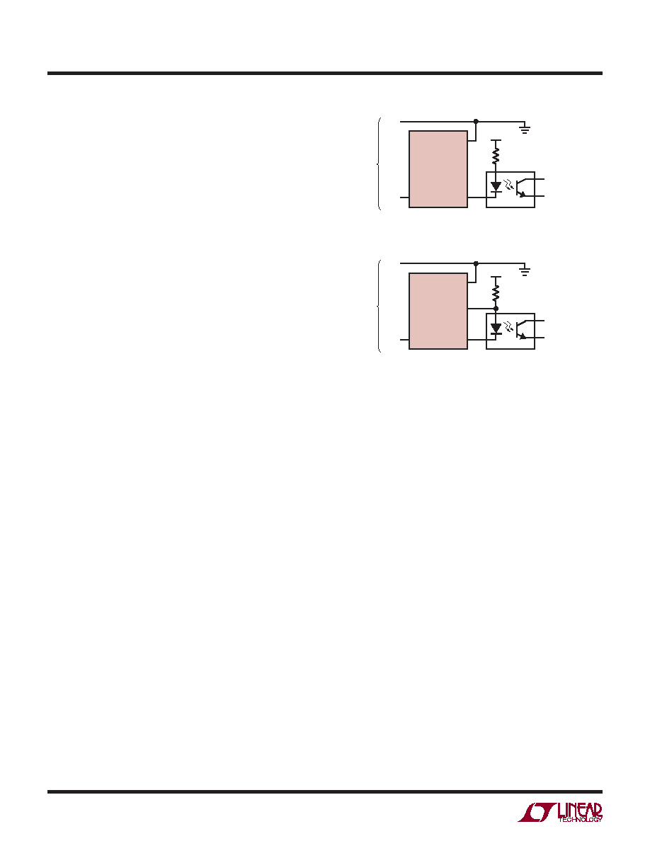
Figure 8 shows two interface options using the T2P pin
and the opto-isolator. The T2P pin is active low and con-
nects to an opto-isolator to communicate across the DC/
DC converter isolation barrier. The pull-up resistor RP is
sized according to the requirements of the opto-isolator
operating current, the pull-down capability of the T2P pin,
and the choice of V+. V+ for example can come from the
PoE supply rail (which the LTC4278 VPORTP is tied to), or
from the voltage source that supplies power to the DC/
DC converter. Option 1 has the advantage of not drawing
power unless T2P is declared active.
Shutdown Interface
To corrupt the signature resistance, the SHDN pin can be
driven high with respect to VPORTN. If unused, connect
SHDN directly to VPORTN.
Auxiliary Power Source
In some applications, it is desirable to power the PD from
an auxiliary power source such as a wall adapter.
Auxiliary power can be injected into an LTC4278-based
PD at the input of the LTC4278 VPORTN, at VNEG, or even
the power supply output. In addition, some PD applications
maydesireauxiliarysupplydominanceormaybeconfigured
APPLICATIONS INFORMATION
4278 F08
OPTION 1: SERIES CONFIGURATION FOR ACTIVE LOW/LOW IMPEDANCE OUTPUT
–54V
TO
PSE
RP
TO PD LOAD
VPORTP
LTC4278
VPORTN
T2P
V+
OPTION 2: SHUNT CONFIGURATION FOR ACTIVE HIGH/OPEN COLLECTOR OUTPUT
–54V
TO
PSE
RP
TO PD LOAD
VPORTP
LTC4278
VPORTN
VNEG
T2P
V+
Figure 8. T2P Interface Examples
相关PDF资料 |
PDF描述 |
|---|---|
| H3BKH-2006M | IDC CABLE - HSR20H/AE20M/HPK20H |
| RBM18DCTD-S288 | CONN EDGECARD 36POS .156 EXTEND |
| REC5-4815DRW/H6/A | CONV DC/DC 5W 36-72VIN +/-15VOUT |
| V110C24C100B | CONVERTER MOD DC/DC 24V 100W |
| RSA06DRST-S288 | CONN EDGECARD 12POS .125 EXTEND |
相关代理商/技术参数 |
参数描述 |
|---|---|
| DC1561W | 制造商:Aleph America Corporation 功能描述: |
| DC1561W-COM | 制造商:Aleph America Corporation 功能描述: |
| DC1562A-A | 功能描述:BOARD EVAL LTC6990 RoHS:是 类别:编程器,开发系统 >> 评估演示板和套件 系列:TimerBlox® 标准包装:1 系列:- 主要目的:电信,线路接口单元(LIU) 嵌入式:- 已用 IC / 零件:IDT82V2081 主要属性:T1/J1/E1 LIU 次要属性:- 已供物品:板,电源,线缆,CD 其它名称:82EBV2081 |
| DC1562A-B | 功能描述:BOARD EVAL LTC6991 RoHS:是 类别:编程器,开发系统 >> 评估演示板和套件 系列:TimerBlox® 标准包装:1 系列:- 主要目的:电信,线路接口单元(LIU) 嵌入式:- 已用 IC / 零件:IDT82V2081 主要属性:T1/J1/E1 LIU 次要属性:- 已供物品:板,电源,线缆,CD 其它名称:82EBV2081 |
| DC1562A-C | 功能描述:BOARD EVAL LTC6992-1 RoHS:是 类别:编程器,开发系统 >> 评估演示板和套件 系列:TimerBlox® 标准包装:1 系列:- 主要目的:数字电位器 嵌入式:- 已用 IC / 零件:AD5258 主要属性:- 次要属性:- 已供物品:板 相关产品:AD5258BRMZ1-ND - IC POT DGTL I2C1K 64P 10MSOPAD5258BRMZ10-ND - IC POT DGTL I2C 10K 64P 10MSOPAD5258BRMZ100-ND - IC POT DGTL I2C 100K 64P 10MSOPAD5258BRMZ50-ND - IC POT DGTL I2C 50K 64P 10MSOPAD5258BRMZ1-R7-ND - IC POT DGTL I2C 1K 64P 10MSOPAD5258BRMZ10-R7-ND - IC POT DGTL I2C 10K 64P 10MSOPAD5258BRMZ50-R7-ND - IC POT DGTL I2C 50K 64P 10MSOPAD5258BRMZ100-R7-ND - IC POT DGTL I2C 100K 64P 10MSOP |
发布紧急采购,3分钟左右您将得到回复。