- 您现在的位置:买卖IC网 > PDF目录258144 > DG190AP (VISHAY SILICONIX) DUAL 1-CHANNEL, SGL POLE DOUBLE THROW SWITCH, DIP16 PDF资料下载
参数资料
| 型号: | DG190AP |
| 厂商: | VISHAY SILICONIX |
| 元件分类: | 多路复用及模拟开关 |
| 英文描述: | DUAL 1-CHANNEL, SGL POLE DOUBLE THROW SWITCH, DIP16 |
| 封装: | SIDE BRAZED, DIP-16 |
| 文件页数: | 5/9页 |
| 文件大小: | 109K |
| 代理商: | DG190AP |
DG189/190/191
Vishay Siliconix
Document Number: 70034
S-51140—Rev. D, 20-Jun-05
www.vishay.com
5
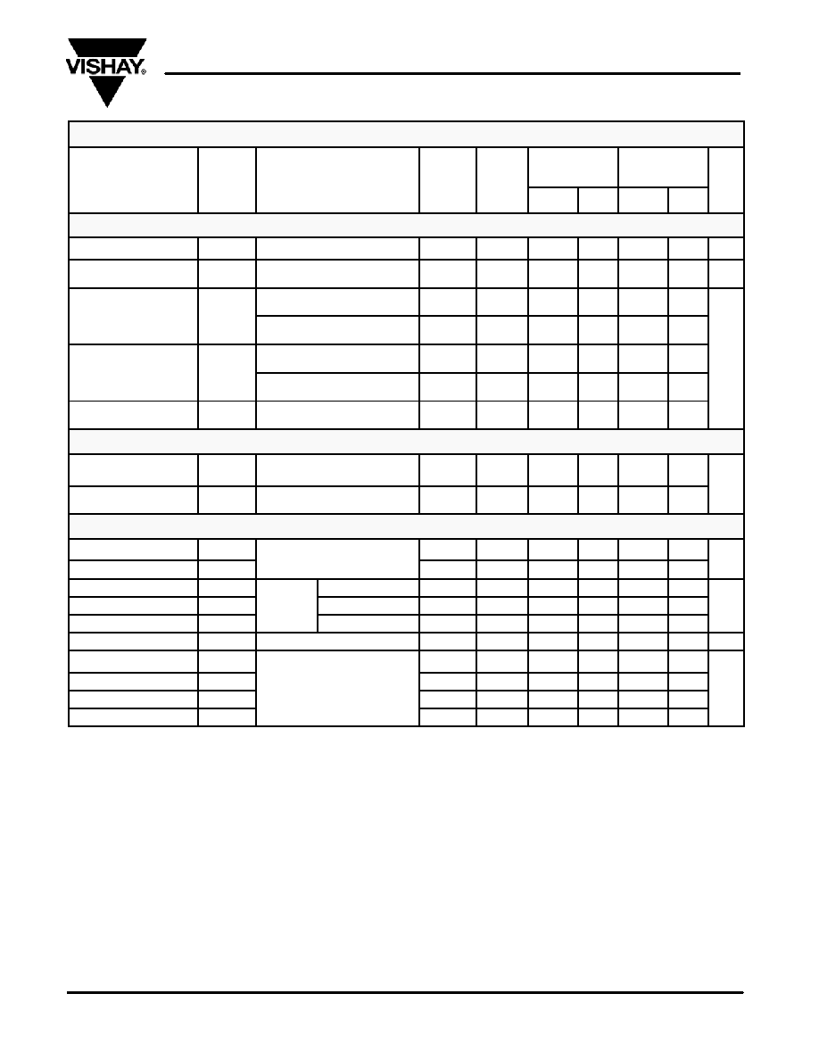
SPECIFICATIONSa FOR DG191
Test Conditions
Unless Specified
A Suffix
55 to 125_C
B Suffix
25 to 85_C
Parameter
Symbol
V+ = 15 V, V = 15 V, VL = 5 V
Tempb
Typc
Maxd
Mind
Maxd Unit
Analog Switch
Analog Signal Rangee
VANALOG
Full
10
15
10
15
V
Drain-Source
On-Resistance
rDS(on)
IS = 10 mA, VD = 7.5 V
Room
Full
35
75
150
100
150
W
Source Off
IS( ff)
VS = "10 V, VD = #10 V
V+ = 10 V, V = 20 V
Room
Hot
0.05
1
100
5
100
Source Off
Leakage Current
IS(off)
VS = "10 V, VD = #10 V
Room
Hot
0.07
1
100
5
100
Drain Off
ID( ff)
VS = "10 V, VD = #10 V
V+ = 10 V, V = 20 V
Room
Hot
0.04
1
100
5
100
nA
Drain Off
Leakage Current
ID(off)
VS = "10 V, VD = #10 V
Room
Hot
0.05
1
100
5
100
Channel On
Leakage Current
ID(on)
VD = VS = "10 V
Room
Hot
0.03
2
200
10
200
Digital Input
Input Current with
Input Voltage High
IINH
VIN = 5 V
Room
Hot
<0.01
10
20
10
20
mA
Input Current with
Input Voltage Low
IINL
VIN = 0 V
Full
30
250
mA
Dynamic Characteristics
Turn-On Time
ton
See Switching Time Test Circuit
Room
120
250
300
ns
Turn-Off Time
toff
See Switching Time Test Circuit
Room
100
130
150
ns
Source-Off Capacitance
CS(off)
VS = 5 V, ID = 0
Room
9
Drain-Off Capacitance
CD(off)
f = 1 MHz
VD = 5 V, IS = 0
Room
6
pF
Channel-On Capacitance
CD(on)
VD = VS = 0 V
Room
14
p
Off Isolation
OIRR
f = 1 MHz, RL = 75 W
Room
>50
dB
Positive Supply Current
I+
Room
0.6
1.5
Negative Supply Current
I
VIN = 0 V or 5 V
Room
2.7
5
mA
Logic Supply Current
IL
VIN = 0 V, or 5 V
Room
3.1
4.5
mA
Reference Supply Current
IR
Room
1
2
Notes:
a.
Refer to PROCESS OPTION FLOWCHART.
b.
Room = 25_C, Full = as determined by the operating temperature suffix.
c.
Typical values are for DESIGN AID ONLY, not guaranteed nor subject to production testing.
d.
The algebraic convention whereby the most negative value is a minimum and the most positive a maximum, is used in this data sheet.
e.
Guaranteed by design, not subject to production test.
f.
VIN = input voltage to perform proper function.
相关PDF资料 |
PDF描述 |
|---|---|
| DRS4812-8 | 1-OUTPUT 1.25 W DC-DC REG PWR SUPPLY MODULE |
| DRS512-8 | 1-OUTPUT 1.25 W DC-DC REG PWR SUPPLY MODULE |
| DLV-3.3/6-1.5/7-D12TSN | 2-OUTPUT DC-DC REG PWR SUPPLY MODULE |
| DLV-3.3/6-1.8/7-D12SN | 2-OUTPUT 30 W DC-DC REG PWR SUPPLY MODULE |
| DG201HSK | 4-CHANNEL, SGL POLE SGL THROW SWITCH, CDIP |
相关代理商/技术参数 |
参数描述 |
|---|---|
| DG190AP/883 | 制造商:Vishay Angstrohm 功能描述:Analog Switch Dual SPDT 16-Pin SBCDIP |
| DG190AP/883B | 制造商:INTERSIL 制造商全称:Intersil Corporation 功能描述:High-Speed Drivers with JFET Switch |
| DG190AP/B | 制造商:Rochester Electronics LLC 功能描述: |
| DG190AP\883 | 制造商:Vishay Siliconix 功能描述:ANALOG SWITCH IC |
| DG190AUHVA-SAW-E-X | 制造商:SMART Modular Technology Inc 功能描述:19"LCD DISPLAY - Trays |
发布紧急采购,3分钟左右您将得到回复。