参数资料
| 型号: | DM300021 |
| 厂商: | Microchip Technology |
| 文件页数: | 26/60页 |
| 文件大小: | 0K |
| 描述: | MODULE PWR DSPICDEM MC1H HV 3PHS |
| 标准包装: | 1 |
| 主要目的: | 电源管理,电机控制 |
| 嵌入式: | 是,MCU,16 位 |
| 已用 IC / 零件: | dsPIC33FJxxxMC |
| 主要属性: | 3 相高压电源模块 |
| 次要属性: | 运动传感器输入:霍尔传感器或光学编码器 |
| 已供物品: | 子板 |
第1页第2页第3页第4页第5页第6页第7页第8页第9页第10页第11页第12页第13页第14页第15页第16页第17页第18页第19页第20页第21页第22页第23页第24页第25页当前第26页第27页第28页第29页第30页第31页第32页第33页第34页第35页第36页第37页第38页第39页第40页第41页第42页第43页第44页第45页第46页第47页第48页第49页第50页第51页第52页第53页第54页第55页第56页第57页第58页第59页第60页
�� �
�
�dsPICDEM?� MC1H� 3-Phase� High� Voltage� Power� Module�
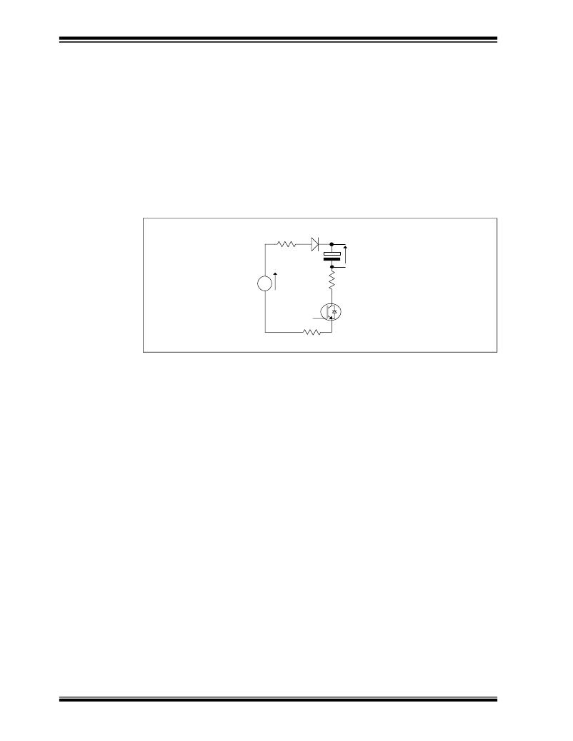
�The� function� of� groups� of� the� discrete� gate-drive� components� is� explained� below:�
�?� R51,� D28,� C14,� C17� –� These� components� form� a� floating� power� supply� for� the�
�high� side� gate� driving� stage� of� U22.� Whenever� the� low� side� IGBT� (Q4)� or� it's�
�anti-parallel� diode� is� conducting;� a� charging� path� for� C14� and� C17� is� formed.� This�
�is� because� the� 15V� supply� is� referenced� to� the� -DC� bus� and� D28� conducts.� When�
�the� high� side� switch� is� on,� and� the� low� side� switch� is� therefore� off,� D28� blocks�
�reverse� current� flow� that� would� result� from� the� bus� voltage� present� on� the� inverter�
�output.� This� kind� of� floating� supply� is� usually� referred� to� as� a� “bootstrap”,� see�
��economical.� It� is� assumed� that� any� bootstrap� initial� priming� or� any� necessary�
�refresh� is� carried� out� in� software� by� the� dsPIC� device.� This� is� discussed� in�
��FIGURE� 1-7:�
�BOOTSTRAP� SUPPLY�
�R51�
�D28�
�15V�
�C17�
�Bootstrap�
�Supply�
�R38�
�Q4�
�R4�
�?� R33,� D21,� R39� and� R38� –� These� components� aid� in� the� correct� control� of� the� gate�
�of� the� high� side� power� device.� The� same� circuit� is� repeated� for� the� low� side� switch�
�using� R54,� D27,� R57� and� R58.� Generally� speaking,� the� larger� value� of� gate�
�resistance� used,� the� slower� the� device� switches.� Slower� switching� reduces�
�over/undershoots� and� consequently� EMI,� but� increases� switching� loss� and� hence�
�device� junction� temperature.� Turning� the� device� on� uses� R39� and� R38.� Turning�
�the� device� off� uses� D21+R33� in� parallel� with� R39� and� R38.� In� this� way,� different�
�turn� on� and� turn� off� resistance� can� be� used� to� optimize� switching� performance.�
�?� D31� –� This� is� a� high� voltage� clamping� diode� located� directly� adjacent� to� the� IC.� It�
�is� necessary� to� ensure� correct� operation� of� the� IC� during� extreme� transients� that�
�can� occur� during� a� FAULT.� In� combination� with� R38� and� R53,� it� ensures� Pin6� of�
�U22� never� goes� more� than� 5V� negative� with� respect� to� Pin2.�
�?� R27� and� R26� –� These� resistors� form� a� passive� Gate� Emitter� pull-down� to� ensure�
�the� IGBTs� stay� off� if� the� low� voltage� power� supplies� are� not� present.�
�1.4.4�
�Brake� Chopper� (Appendix� A,� Sheet� 1)�
�Clearly,� if� the� motor� is� used� as� a� brake� or� generator,� any� average� power� that� flows�
�back� from� the� inverter� must� have� somewhere� to� go.� As� the� mains� input� and� power�
�conditioning� stages� have� only� been� designed� for� importing� power,� a� means� of�
�dissipating� the� excess� power� has� been� provided.� The� most� common� form� of� brake�
�chopper� has� been� implemented� and� is� described� below:�
�?� Q10� –� A� 600V� N-Channel� IGBT� transistor� with� anti-parallel� diode.� This� is� of� the�
�same� type� as� used� for� the� inverter� for� economic� reasons.� In� practice� a� slower�
�switching� device� may� be� used� which� has� lower� conduction� loss.� Apart� from�
�acoustic� noise� reasons,� there� is� no� reason� to� modulate� the� device� at� high�
�frequency.� As� the� tab� of� the� device� is� not� isolated,� a� thermally� conductive� insulator�
�is� used.�
�DS70096A-page� 20�
�?� 2003� Microchip� Technology� Inc.�
�相关PDF资料 |
PDF描述 |
|---|---|
| DM300022 | MODULE PWR DSPICDEM MC1L LV 3PHS |
| DM320002 | BOARD EXPANSION PIC32 I/O |
| DM320003-2 | KIT EVAL PIC32 USB II STARTER |
| DM320003 | BOARD DEMO USB PIC32 OTG |
| DM320005 | BOARD EXPANSION FOR PIC32 KIT |
相关代理商/技术参数 |
参数描述 |
|---|---|
| DM300021 | 制造商:Microchip Technology Inc 功能描述:MODULE dsPICDEM MC1H 3 PHASE |
| DM300022 | 功能描述:开发板和工具包 - PIC / DSPIC Low V Pwr Module RoHS:否 制造商:Microchip Technology 产品:Starter Kits 工具用于评估:chipKIT 核心:Uno32 接口类型: 工作电源电压: |
| DM300023 | 功能描述:开发板和工具包 - PIC / DSPIC dsPICDEM SMPS Buck Demo Brd RoHS:否 制造商:Microchip Technology 产品:Starter Kits 工具用于评估:chipKIT 核心:Uno32 接口类型: 工作电源电压: |
| DM300024 | 功能描述:开发板和工具包 - PIC / DSPIC dsPICDEM 1.1 GP RoHS:否 制造商:Microchip Technology 产品:Starter Kits 工具用于评估:chipKIT 核心:Uno32 接口类型: 工作电源电压: |
| DM300027 | 功能描述:开发板和工具包 - PIC / DSPIC 16-bit Starter Demo Board RoHS:否 制造商:Microchip Technology 产品:Starter Kits 工具用于评估:chipKIT 核心:Uno32 接口类型: 工作电源电压: |
发布紧急采购,3分钟左右您将得到回复。