- 您现在的位置:买卖IC网 > PDF目录1993 > DS1124U-25+T (Maxim Integrated Products)IC DELAY LINE 256TAP 10-USOP PDF资料下载
参数资料
| 型号: | DS1124U-25+T |
| 厂商: | Maxim Integrated Products |
| 文件页数: | 7/10页 |
| 文件大小: | 0K |
| 描述: | IC DELAY LINE 256TAP 10-USOP |
| 产品培训模块: | Lead (SnPb) Finish for COTS Obsolescence Mitigation Program |
| 标准包装: | 3,000 |
| 标片/步级数: | 256 |
| 功能: | 可编程 |
| 延迟到第一抽头: | 20ns |
| 接头增量: | 0.25ns |
| 可用的总延迟: | 83.75ns |
| 独立延迟数: | 1 |
| 电源电压: | 4.75 V ~ 5.25 V |
| 工作温度: | -40°C ~ 85°C |
| 安装类型: | 表面贴装 |
| 封装/外壳: | 10-TFSOP,10-MSOP(0.118",3.00mm 宽) |
| 供应商设备封装: | 10-µMAX |
| 包装: | 带卷 (TR) |
DS1124
Detailed Description
The DS1124 is an 8-bit programmable delay line that
can be adjusted between 256 different delay intervals.
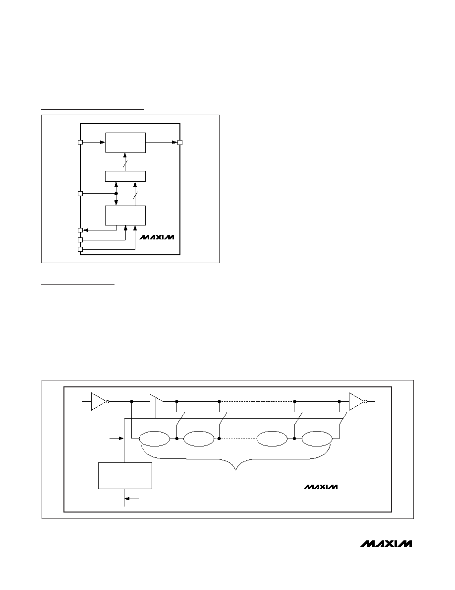
The DS1124 architecture (see Figure 2) allows some
signals to be delayed by more than one period, which
lets the phase of the signal to be adjusted up to a full
360°. Programming is performed by a 3-wire serial
interface. Using the 3-wire interface, it is possible to
cascade multiple devices together for systems requir-
ing multiple programmable delays without using addi-
tional I/O resources.
Using the Serial Programming Interface
Serial mode operates similar to a shift register. When the
E pin is set at a high logic level, it enables the shift regis-
ter and CLK clocks the data, D, into the register one bit at
a time starting with the most significant bit. After all 8 bits
are shifted into the DS1124, E must be pulled low to end
the data transfer and activate the new value. A settling
time (tEDV) is required after E is pulled low before the
signal delay will meet its specified accuracy. A timing
diagram for the serial interface is shown in Figure 3.
The 3-wire interface also has an output (Q) that can be
used to cascade multiple 3-wire devices, and it can be
used to read the current value of the devices on the
bus. To read the current values stored by the 3-wire
device(s), the latch must be enabled and the value of Q
must be read and then written back to D before the reg-
ister is clocked. This causes the current value of the
register to be written back into the DS1124 as it is
being read. This can be accomplished in a couple of
different ways. If the microprocessor has an I/O pin that
is high impedance when set as an input, a feedback
resistor (RFB, generally between 1k
Ω and 10kΩ) can be
used to write the data on Q back to D as the value is
read, see Figure 4A. If the microprocessor has an inter-
nal pullup on its I/O pins, or only offers separate input
and output pins, the value in the register can still be
read. The circuit shown in Figure 4B allows the Q val-
ues to read by the microprocessor, which must write
the Q value to D before it can clock the bus to read the
next bit. If the Q values are read without writing them to
D (with the pullup or otherwise), the read will be
destructive. A destructive read cycle likely results in an
undesirable change in the delay setting.
5.0V 8-Bit Programmable
Timing Element
6
_______________________________________________________________________________________
Block Diagram
8-BIT LATCH
8-BIT SHIFT
REGISTER
PROGRAMMABLE
DELAY
8
Q
CLK
D
OUT
IN
E
8
DS1124
tSTEP
256 CONTROL LINES
8-BIT LATCH VALUE
255 UNIT DELAY CELLS
256 LINE DECODER
IN
OUT
DS1124
Figure 2. Conceptual Design
相关PDF资料 |
PDF描述 |
|---|---|
| DS1135LU-300/T&R | IC DELAY LINE 300NS 8-USOP |
| DS1135Z-12/T&R | IC DELAY LINE 12NS 8-SOIC |
| DS1181LE+ | IC CLOCK MOD SS 8-TSSOP |
| DS1243Y-120 | IC NVSRAM 64KBIT 120NS 28DIP |
| DS1244W-120IND | IC NVSRAM 256KBIT 120NS 28DIP |
相关代理商/技术参数 |
参数描述 |
|---|---|
| DS112-B | 制造商:Cooper Hand Tools / Weller 功能描述: |
| DS1-12D | 功能描述:二极管 - 通用,功率,开关 1 Amps 1200V RoHS:否 制造商:STMicroelectronics 产品:Switching Diodes 峰值反向电压:600 V 正向连续电流:200 A 最大浪涌电流:800 A 配置: 恢复时间:2000 ns 正向电压下降:1.25 V 最大反向漏泄电流:300 uA 最大功率耗散: 工作温度范围: 安装风格:SMD/SMT 封装 / 箱体:ISOTOP 封装:Tube |
| DS112HM | 制造商:Cooper Tools / Weller 功能描述:Bulk 制造商:Cooper Hand Tools / Weller 功能描述:NOZZLE METRIC 1.0MM 制造商:WELLER 功能描述:NOZZLE, METRIC, 1.0MM |
| DS112PIN | 制造商:未知厂家 制造商全称:未知厂家 功能描述:Industrial Control IC |
| DS-112PIN | 制造商:MA-COM 制造商全称:M/A-COM Technology Solutions, Inc. 功能描述:Four-Way Power Dividers 10 - 500 MHz |
发布紧急采购,3分钟左右您将得到回复。