- 您现在的位置:买卖IC网 > PDF目录97860 > DS1315E-5 (DALLAS SEMICONDUCTOR) 0 TIMER(S), REAL TIME CLOCK, PDSO20 PDF资料下载
参数资料
| 型号: | DS1315E-5 |
| 厂商: | DALLAS SEMICONDUCTOR |
| 元件分类: | Timer or RTC |
| 英文描述: | 0 TIMER(S), REAL TIME CLOCK, PDSO20 |
| 封装: | TSSOP-20 |
| 文件页数: | 17/21页 |
| 文件大小: | 523K |
| 代理商: | DS1315E-5 |
DS1315
5 of 21
NONVOLATILE CONTROLLER OPERATION
The operation of the nonvolatile controller circuits within the Time Chip is determined by the level of the
ROM/ RAM select pin. When ROM/ RAM is connected to ground, the controller is set in the RAM mode
and performs the circuit functions required to make CMOS RAM and the timekeeping function
nonvolatile. A switch is provided to direct power from the battery inputs or VCCI to VCCO with a
maximum voltage drop of 0.3 volts. The VCCO output pin is used to supply uninterrupted power to CMOS
SRAM. The DS1315 also performs redundant battery control for high reliability. On power-fail, the
battery with the highest voltage is automatically switched to VCCO. If only one battery is used in the
system, the unused battery input should be connected to ground.
The DS1315 safeguards the Time Chip and RAM data by power-fail detection and write protection.
Power-fail detection occurs when VCCI falls below VPF which is set by an internal bandgap reference. The
DS1315 constantly monitors the VCCI supply pin. When VCCI is less than VPF, power-fail circuitry forces
the chip enable output ( CEO ) to VCCI or VBAT-0.2 volts for external RAM write protection. During
nominal supply conditions, CEO will track CEI with a propagation delay. Internally, the DS1315 aborts
any data transfer in progress without changing any of the Time Chip registers and prevents future access
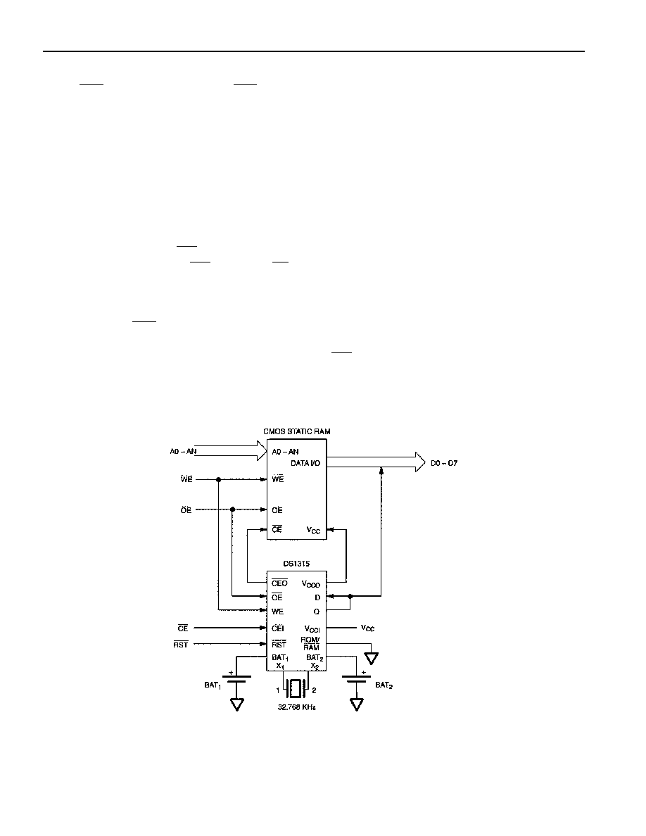
until VCCI exceeds VPF. A typical RAM/Time Chip interface is illustrated in Figure 3.
When the ROM/ RAM pin is connected to VCCO, the controller is set in the ROM mode. Since ROM is a
read-only device that retains data in the absence of power, battery backup and write protection is not
required. As a result, the chip enable logic will force CEO low when power fails. However, the Time
Chip does retain the same internal nonvolatility and write protection as described in the RAM mode. A
typical ROM/Time Chip interface is illustrated in Figure 4.
DS1315 TO RAM/TIME CHIP INTERFACE Figure 3
相关PDF资料 |
PDF描述 |
|---|---|
| DS1315SN-33 | 0 TIMER(S), REAL TIME CLOCK, PDSO16 |
| DS1330ABP-100 | 32K X 8 NON-VOLATILE SRAM MODULE, 100 ns, DMA34 |
| DS1330YP-100 | 32K X 8 NON-VOLATILE SRAM MODULE, 100 ns, DMA34 |
| DS1330ABP-70 | 32K X 8 NON-VOLATILE SRAM MODULE, 70 ns, DMA34 |
| DS1330WP-150 | 32K X 8 NON-VOLATILE SRAM MODULE, 150 ns, DMA34 |
相关代理商/技术参数 |
参数描述 |
|---|---|
| DS1315E-5+ | 功能描述:实时时钟 Phantom Time Chip RoHS:否 制造商:Microchip Technology 功能:Clock, Calendar. Alarm RTC 总线接口:I2C 日期格式:DW:DM:M:Y 时间格式:HH:MM:SS RTC 存储容量:64 B 电源电压-最大:5.5 V 电源电压-最小:1.8 V 最大工作温度:+ 85 C 最小工作温度: 安装风格:Through Hole 封装 / 箱体:PDIP-8 封装:Tube |
| DS1315E-5V | 制造商:未知厂家 制造商全称:未知厂家 功能描述:Real-Time Clock |
| DS1315EN-33 | 功能描述:实时时钟 RoHS:否 制造商:Microchip Technology 功能:Clock, Calendar. Alarm RTC 总线接口:I2C 日期格式:DW:DM:M:Y 时间格式:HH:MM:SS RTC 存储容量:64 B 电源电压-最大:5.5 V 电源电压-最小:1.8 V 最大工作温度:+ 85 C 最小工作温度: 安装风格:Through Hole 封装 / 箱体:PDIP-8 封装:Tube |
| DS1315EN-33/R | 制造商:DALLAS 制造商全称:Dallas Semiconductor 功能描述:Phantom Time Chip |
| DS1315EN-33/T | 制造商:DALLAS 制造商全称:Dallas Semiconductor 功能描述:Phantom Time Chip |
发布紧急采购,3分钟左右您将得到回复。