- 您现在的位置:买卖IC网 > PDF目录1993 > DS1384FP-12+ (Maxim Integrated Products)IC CTRLR RTC WDOG 120NS 44-MQFP PDF资料下载
参数资料
| 型号: | DS1384FP-12+ |
| 厂商: | Maxim Integrated Products |
| 文件页数: | 12/18页 |
| 文件大小: | 0K |
| 描述: | IC CTRLR RTC WDOG 120NS 44-MQFP |
| 标准包装: | 96 |
| 类型: | 时钟/日历 |
| 特点: | 警报器,闰年,方波输出,监视计时器 |
| 存储容量: | 50B |
| 时间格式: | HH:MM:SS:hh(12/24 小时) |
| 数据格式: | YY-MM-DD-dd |
| 接口: | 并联 |
| 电源电压: | 4.5 V ~ 5.5 V |
| 电压 - 电源,电池: | 2.4 V ~ 4 V |
| 工作温度: | 0°C ~ 70°C |
| 安装类型: | 表面贴装 |
| 封装/外壳: | 44-QFP |
| 供应商设备封装: | 44-MQFP(10x10) |
| 包装: | 托盘 |
DS1384
3 of 18
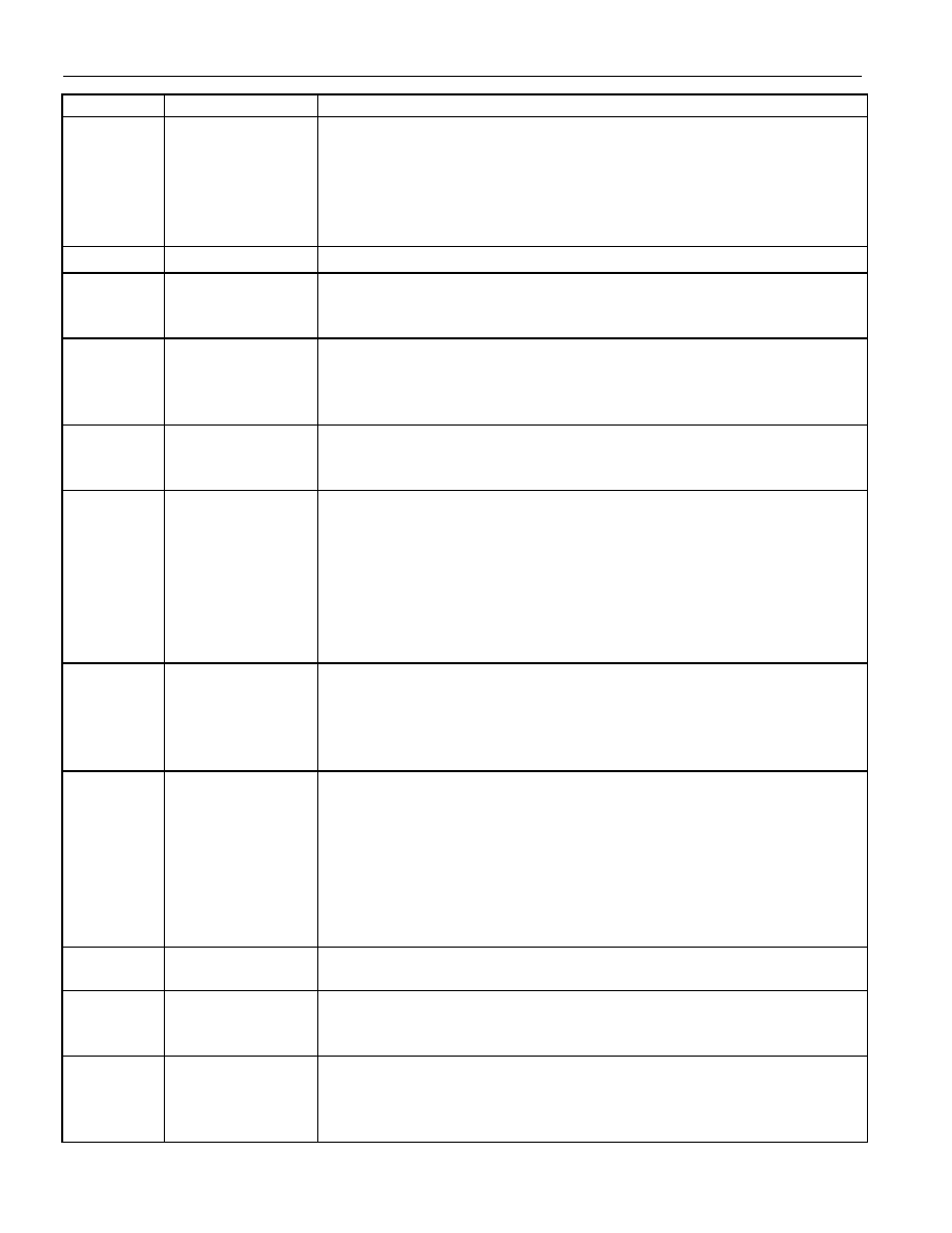
PIN
NAME
FUNCTION
13, 14, 15,
17–21
DQ0, DQ1, DQ2,
DQ3–DQ7
Data Bus (Bidirectional). When a qualified address from 00000H–
0003FH is presented to the device, data is passed to or from the on-
chip 64 timekeeping/RAM registers via the data bus lines. Data is
written on the rising edge of
WE when CE is active. If CE is active
without
WE, data is read from the device and driven onto the data bus
pins when
OE is low.
16, 41, 44
GND
Ground. DC power input.
22
CEO
Active-Low RAM Chip-Enable Output. When power is good, the
CE
input is passed through to
CEO. If VCC is below VPF, CEO remains at
an inactive high level.
23
OER
Active-Low RAM Output Enable (Output). When power is good and
the address value is not within the range of 00000H and 0003FH, and
CE is active, the OE input is passed through to OER. If these
conditions are not met,
OER remains at an inactive high level.
24
CE
Active-Low Chip Enable (Input). This signal must be asserted low
during a bus cycle to access the on-chip timekeeping RAM registers,
or to access the external RAM via
CEO.
26
OE
Active-Low Output Enable (Input). This signal identifies the time
period when either the RTC or the external SRAM drives the bus with
read data, provided that
CE is valid with WE disabled. When one of
the 64 on-chip registers is selected during a read cycle, the
OE is the
enable signal for the DS1384 output buffers and the data bus is driven
with read data. When the external RAM is selected during a read
cycle, the
OE signal is passed through to the OER pin so that read data
is driven by the external SRAM.
31
WE
Active-Low Write Enable (Input). This signal identifies the time
period during which data is written to either the on-chip registers or to
an external SRAM location. When one of the on-chip 64 registers is
addressed, data is written to the selected register on the rising edge of
WE.
32, 34
VBAT1, VBAT2
Battery Inputs for Any Standard 3V Lithium Cell or Other Energy
Source. Battery voltage must be held between 2.4V and 4V for proper
operation. In the absence of power, the DS1384 has a maximum load
of 0.5
A at +25°C. This should be added to the amount of current
drawn from the external RAM in standby mode at +25
°C to size the
external energy source. The DS1384 samples VBAT1 and VBAT2 and
always selects the battery with the higher voltage. If only one battery
is used, the unused battery input must be grounded.
35
PFO
Power-Fail Signal (Output, Active Low when VWP Occurs). High state
occurs tREC after power-up and VCC ≥ 4.5V.
36
SQW
Square-Wave Output. This pin can be programmed to output a
1024Hz square-wave signal. When the signal is turned off, the pin is
high impedance.
37
VCCO
Switched DC Power for SRAM (Output). This pin is connected to VCC
when VCC voltage is above VSO (the greater of VBAT1 or VBAT2). When
VCC voltage falls below this level, VCCO is connected to the higher
voltage battery pin.
相关PDF资料 |
PDF描述 |
|---|---|
| DS1386P-8-120+ | IC TIMEKEEPER RAM 64K 34-PCM |
| DS1388Z-3+T&R | IC RTC I2C W/CHARGER 8-SOIC |
| DS1391U-3+ | IC RTC W/CHARGER 10-USOP |
| DS1394U-33+T&R | IC RTC SPI 3WIRE W/CHRGR 10-MSOP |
| DS14285SN+T&R | IC RTC W/NV RAM CNTRL 24-SOIC |
相关代理商/技术参数 |
参数描述 |
|---|---|
| DS1384FP-12+ | 功能描述:实时时钟 RoHS:否 制造商:Microchip Technology 功能:Clock, Calendar. Alarm RTC 总线接口:I2C 日期格式:DW:DM:M:Y 时间格式:HH:MM:SS RTC 存储容量:64 B 电源电压-最大:5.5 V 电源电压-最小:1.8 V 最大工作温度:+ 85 C 最小工作温度: 安装风格:Through Hole 封装 / 箱体:PDIP-8 封装:Tube |
| DS1384FP-120 | 制造商:未知厂家 制造商全称:未知厂家 功能描述:Real-Time Clock |
| DS1384T-120 | 制造商:未知厂家 制造商全称:未知厂家 功能描述:Real-Time Clock |
| DS1384T-150 | 制造商:未知厂家 制造商全称:未知厂家 功能描述:Real-Time Clock |
| DS1385 | 制造商:DALLAS 制造商全称:Dallas Semiconductor 功能描述:RAMified Real Time Clock 4K x 8 |
发布紧急采购,3分钟左右您将得到回复。