- 您现在的位置:买卖IC网 > PDF目录9173 > DS1859B-020+T&R (Maxim Integrated Products)IC RES TEMP 20/20K W/3MON 16-BGA PDF资料下载
参数资料
| 型号: | DS1859B-020+T&R |
| 厂商: | Maxim Integrated Products |
| 文件页数: | 16/28页 |
| 文件大小: | 0K |
| 描述: | IC RES TEMP 20/20K W/3MON 16-BGA |
| 产品培训模块: | Lead (SnPb) Finish for COTS Obsolescence Mitigation Program |
| 标准包装: | 2,500 |
| 接片: | 256 |
| 电阻(欧姆): | 20k |
| 电路数: | 2 |
| 温度系数: | 标准值 50 ppm/°C |
| 存储器类型: | 非易失 |
| 接口: | I²C(设备位址) |
| 电源电压: | 2.85 V ~ 5.5 V |
| 工作温度: | -40°C ~ 95°C |
| 安装类型: | 表面贴装 |
| 封装/外壳: | 16-LBGA,CSPBGA |
| 供应商设备封装: | 16-CSBGA(4x4) |
| 包装: | 带卷 (TR) |
第1页第2页第3页第4页第5页第6页第7页第8页第9页第10页第11页第12页第13页第14页第15页当前第16页第17页第18页第19页第20页第21页第22页第23页第24页第25页第26页第27页第28页
DS1859
Dual, Temperature-Controlled Resistors with
Internally Calibrated Monitors
____________________________________________________________________
23
An explanation of the binary search used to scale the
gain is best served with the following example pseudo-
code:
/* Assume that the Null input is 0.5V. */
/* In addition, the requirement for LSB is 50V. */
FS = 65535 x 50E-6;
/* 3.27675 */
CNT1 = 0.5 / 50E-6;
/* 10000 */
CNT2 = 0.90 x FS / 50E-6;
/* 58981.5 */
/* Thus the null input 0.5V and the 90% of FS input is
2.949075V. */
Set the trim-offset-register to zero;
Set Right-Shift register to zero (typically zero.
See Right-Shifting section);
gain_result = 0h;
Clamp = FFF8h/2^(Right_Shift_Register);
For n = 15 down to 0
begin
gain_result = gain_result + 2^n;
Force the 90% FS input (2.949075V);
Meas2 = read the digital result from
the part;
If Meas2 >= Clamp then
gain_result = gain_result – 2^n;
Else
Force the null input (0.5V);
Meas1 = read the digital result from
the part;
if (Meas2 – Meas1) > (CNT2 –
CNT1) then
gain_result = gain_result – 2^n;
end;
Set the gain register to gain_result;
The gain register is now set and the resolution of the
conversion will best match the expected LSB. The next
step is to calibrate the offset of the DS1859. With the
correct gain value written to the gain register, again
force the null input to the pin. Read the digital result
from the part (Meas1). The offset value is equal to the
negative value of Meas1.
The calculated offset is now written to the DS1859 and
the gain and offset scaling is now complete.
Right-Shifting A/D Conversion Result
(Scalable Dynamic Ranging)
The right-shifting method is used to regain some of the
lost ADC range of a calibrated system. If a system is
calibrated such that the maximum expected input
results in a digital output value of less than 7FFFh (1/2
FS), then it is a candidate for using the right-shifting
method.
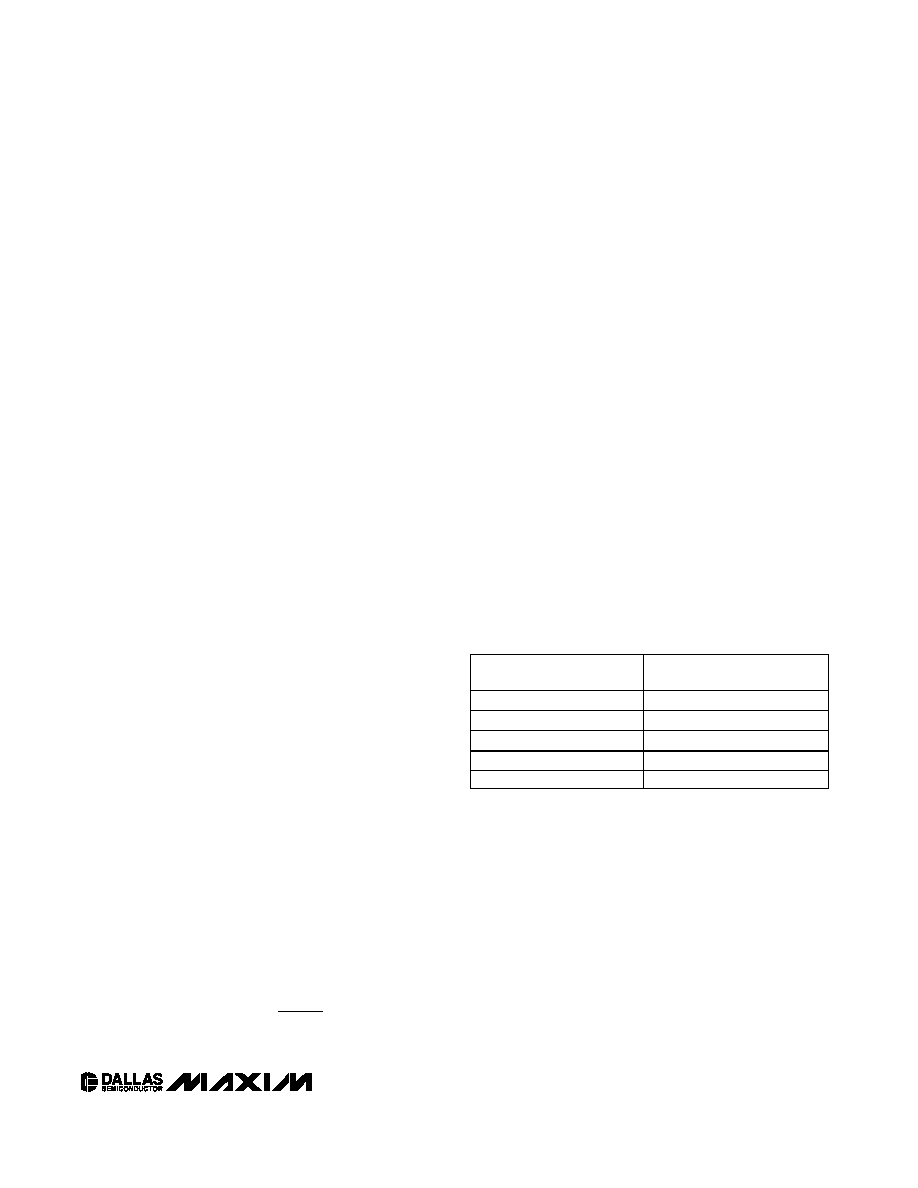
If the maximum desired digital output is less than 7FFFh,
then the calibrated system is using less than 1/2 of the
ADC’s range. Similarly, if the maximum desired digital
output is less than 1FFFh, then the calibrated system is
only using 1/8 of the ADC’s range. For example, if using
a zero for the right-shift during internal calibration and
the maximum expected input results in a maximum digi-
tal output less than 1FFCh, only 1/8 of the ADC’s range is
used. If left like this, the three MS bits of the ADC will
never be used. In this example, a value of 3 for the right-
shifting will maximize the ADC range. No resolution is
lost since this is a 12-bit converter that is left justified.
The value can be right-shifted four times without losing
resolution. Table 9 shows when the right-shifting method
can be used.
Memory Protection
Memory access from either device address can be
either read/write or read only. Write protection
is accomplished by a combination of control bits in
EEPROM (APEN and MPEN in configuration register
89h) and a write-protect enable (WPEN) pin. Since the
WPEN pin is often not accessible from outside the mod-
ule, this scheme effectively allows the module to be
locked by the manufacturer to prevent accidental writes
by the end user.
Separate write protection is provided for the Auxiliary
and Main Device address through distinct bits APEN
and MPEN. APEN and MPEN are bits from configura-
tion register 89h, Table 01. Due to the location, the
APEN and MPEN bits can only be written through the
Offset
gister
h
Meas
XOR
h
_Re
=
[]
4000
1
2
4000
OUTPUT RANGE USED
WITH ZERO RIGHT-SHIFTS
NUMBER OF
RIGHT-SHIFTS NEEDED
0h .. FFFFh
0
0h .. 7FFFh
1
0h .. 3FFFh
2
0h .. 1FFFh
3
0h .. 0FFFh
4
Table 9. Right Shifting
相关PDF资料 |
PDF描述 |
|---|---|
| MS3450L28-2PY | CONN RCPT 14POS WALL MNT W/PINS |
| 74LVX138MX | DECODER/DEMUX 1-OF-8 LV 16SOIC |
| NB3N65027DTR2G | IC CLK SYNTHESIZER 3PLL 20QSOP |
| MM74HCT138MTC | IC DECODER 3-TO-8 LINE 16-TSSOP |
| V28A48H200BL | CONVERTER MOD DC/DC 48V 200W |
相关代理商/技术参数 |
参数描述 |
|---|---|
| DS1859B-020-W | 功能描述:数字电位计 IC RoHS:否 制造商:Maxim Integrated 电阻:200 Ohms 温度系数:35 PPM / C 容差:25 % POT 数量:Dual 每 POT 分接头:256 弧刷存储器:Volatile 缓冲刷: 数字接口:Serial (3-Wire, SPI) 描述/功能:Dual Volatile Low Voltage Linear Taper Digital Potentiometer 工作电源电压:1.7 V to 5.5 V 电源电流:27 uA 最大工作温度:+ 125 C 安装风格:SMD/SMT 封装 / 箱体:TQFN-16 封装:Reel |
| DS1859B-050 | 功能描述:数字电位计 IC RoHS:否 制造商:Maxim Integrated 电阻:200 Ohms 温度系数:35 PPM / C 容差:25 % POT 数量:Dual 每 POT 分接头:256 弧刷存储器:Volatile 缓冲刷: 数字接口:Serial (3-Wire, SPI) 描述/功能:Dual Volatile Low Voltage Linear Taper Digital Potentiometer 工作电源电压:1.7 V to 5.5 V 电源电流:27 uA 最大工作温度:+ 125 C 安装风格:SMD/SMT 封装 / 箱体:TQFN-16 封装:Reel |
| DS1859B-050/T&R | 制造商:Maxim Integrated Products 功能描述:DUAL TMP R 50/50K,3MON,INT CAL T&R - Tape and Reel 制造商:Maxim Integrated Products 功能描述:IC RES TEMP 50/50K W/3MON 16-BGA |
| DS1859B-050/T&R | 功能描述:数字电位计 IC RoHS:否 制造商:Maxim Integrated 电阻:200 Ohms 温度系数:35 PPM / C 容差:25 % POT 数量:Dual 每 POT 分接头:256 弧刷存储器:Volatile 缓冲刷: 数字接口:Serial (3-Wire, SPI) 描述/功能:Dual Volatile Low Voltage Linear Taper Digital Potentiometer 工作电源电压:1.7 V to 5.5 V 电源电流:27 uA 最大工作温度:+ 125 C 安装风格:SMD/SMT 封装 / 箱体:TQFN-16 封装:Reel |
| DS1859B-050+ | 功能描述:数字电位计 IC Dual Temp-Controlled Resistors RoHS:否 制造商:Maxim Integrated 电阻:200 Ohms 温度系数:35 PPM / C 容差:25 % POT 数量:Dual 每 POT 分接头:256 弧刷存储器:Volatile 缓冲刷: 数字接口:Serial (3-Wire, SPI) 描述/功能:Dual Volatile Low Voltage Linear Taper Digital Potentiometer 工作电源电压:1.7 V to 5.5 V 电源电流:27 uA 最大工作温度:+ 125 C 安装风格:SMD/SMT 封装 / 箱体:TQFN-16 封装:Reel |
发布紧急采购,3分钟左右您将得到回复。