- 您现在的位置:买卖IC网 > PDF目录1913 > DS1878T+T&R (Maxim Integrated Products)IC CTLR SFP W/DGTL LDD RX 28TQFN PDF资料下载
参数资料
| 型号: | DS1878T+T&R |
| 厂商: | Maxim Integrated Products |
| 文件页数: | 80/101页 |
| 文件大小: | 0K |
| 描述: | IC CTLR SFP W/DGTL LDD RX 28TQFN |
| 标准包装: | 2,500 |
| 类型: | SFP+ 控制器 |
| 输入类型: | 模拟,数字 |
| 输出类型: | 数字 |
| 接口: | I²C,LDD,串行 |
| 电流 - 电源: | 2.5mA |
| 安装类型: | 表面贴装 |
| 封装/外壳: | 28-WFQFN 裸露焊盘 |
| 供应商设备封装: | 28-TQFN-EP(5x5) |
| 包装: | 带卷 (TR) |
第1页第2页第3页第4页第5页第6页第7页第8页第9页第10页第11页第12页第13页第14页第15页第16页第17页第18页第19页第20页第21页第22页第23页第24页第25页第26页第27页第28页第29页第30页第31页第32页第33页第34页第35页第36页第37页第38页第39页第40页第41页第42页第43页第44页第45页第46页第47页第48页第49页第50页第51页第52页第53页第54页第55页第56页第57页第58页第59页第60页第61页第62页第63页第64页第65页第66页第67页第68页第69页第70页第71页第72页第73页第74页第75页第76页第77页第78页第79页当前第80页第81页第82页第83页第84页第85页第86页第87页第88页第89页第90页第91页第92页第93页第94页第95页第96页第97页第98页第99页第100页第101页
Note 1:
All voltages are referenced to ground. Current into the IC is positive, and current out of the IC is negative.
Note 2:
Inputs are at supply rail. Outputs are not loaded.
Note 3:
Eight ranges allow the full-scale range to change from 312mV to 1.25V.
Note 4:
The output impedance of the device is proportional to its scale setting. For instance, if using the 1/2 scale, the output
impedance is 1.5k
Ω.
Note 5:
This parameter is guaranteed by design.
Note 6:
Full-scale is programmable.
Note 7:
A temperature conversion is completed and the MODULATION register value is recalled from the LUT and VCC has been
measured to be above the VCC LO alarm.
Note 8:
The timing is determined by the choice of the SAMPLE RATE setting (see Table 02h, Register 88h).
Note 9:
This specification is the time it takes from MON3 voltage falling below the LLOS trip threshold to LOSOUT asserted high.
Note 10: This specification is the time it takes from MON3 voltage rising above the HLOS trip threshold to LOSOUT asserted low.
Note 11: Assuming an appropriate initial step is programmed that would cause the power to exceed the APC set point within four
steps, the bias current will be within 3% within the time specified by the binary search time. See the
BIAS and MODULA-
TION Control During Power-Up section.
Note 12: I2C interface timing shown is for fast-mode (400kHz) operation. This device is also backward compatible with I2C stan-
dard-mode timing.
Note 13: CB—the total capacitance of one bus line in pF.
Note 14: EEPROM write begins after a STOP condition occurs.
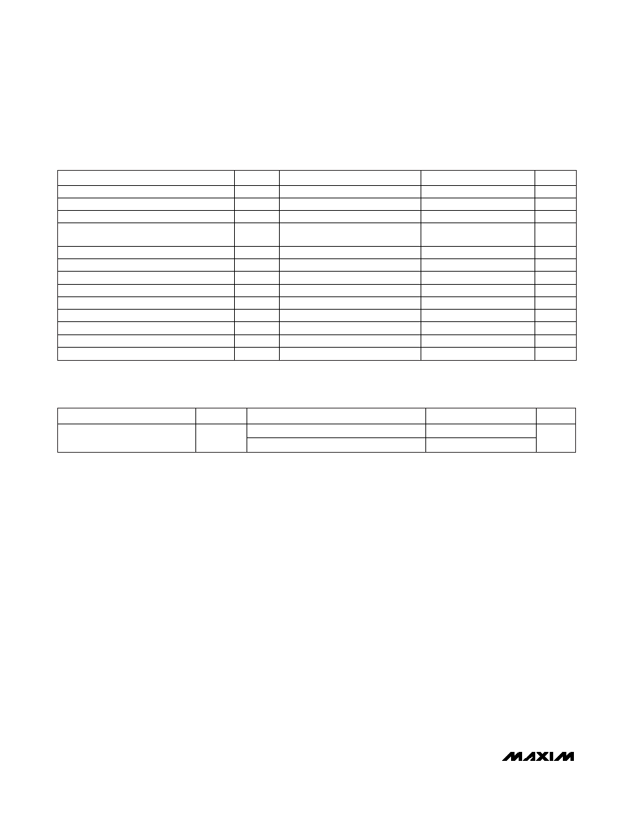
PARAMETER
SYMBOL
CONDITIONS
MIN
TYP
MAX
UNITS
SCL Clock Frequency
fSCL
(Note 12)
0
400
kHz
Clock Pulse-Width Low
tLOW
1.3
μs
Clock Pulse-Width High
tHIGH
0.6
μs
Bus-Free Time Between STOP and START
Condition
tBUF
1.3
μs
START Hold Time
tHD:STA
0.6
μs
START Setup Time
tSU:STA
0.6
μs
Data In Hold Time
tHD:DAT
0
0.9
μs
Data In Setup Time
tSU:DAT
100
ns
Rise Time of Both SDA and SCL Signals
tR
(Note 13)
20 + 0.1CB
300
ns
Fall Time of Both SDA and SCL Signals
tF
(Note 13)
20 + 0.1CB
300
ns
STOP Setup Time
tSU:STO
0.6
μs
Capacitive Load for Each Bus Line
CB
400
pF
EEPROM Write Time
tWR
(Note 14)
20
ms
DS1878
SFP+ Controller with Digital LDD Interface
8
_______________________________________________________________________________________
NONVOLATILE MEMORY CHARACTERISTICS
(VCC = +2.85V to +5.5V, unless otherwise noted.)
PARAMETER
SYMBOL
CONDITIONS
MIN
TYP
MAX
UNITS
At +25°C
200,000
EEPROM Write Cycles
At +85°C
50,000
I2C AC ELECTRICAL CHARACTERISTICS
(VCC = +2.85V to +5.5V, TA = -40°C to +95°C, timing referenced to VIL(MAX) and VIH(MIN), unless otherwise noted.) (Figure 19)
相关PDF资料 |
PDF描述 |
|---|---|
| DS1881Z-050+T&R | IC DGTL POT NV 2CH 45K 16-SOIC |
| DS1882Z-050+T&R | IC POT DIGIT DL LOG 50K 16SOIC |
| DS1884AT+T | IC SFP PON ONU CTRLR 24TQFN |
| DS2105Z+ | IC SCSI TERMINATOR 16-SOIC |
| DS2106S/T&R | IC TERMINATOR SCSI 28-SOIC |
相关代理商/技术参数 |
参数描述 |
|---|---|
| DS-187PU | 制造商:Shinagawa Shoko 功能描述: |
| DS-187U | 制造商:Shinagawa Shoko 功能描述: |
| DS1880E-050 | 功能描述:板上安装温度传感器 RoHS:否 制造商:Omron Electronics 输出类型:Digital 配置: 准确性:+/- 1.5 C, +/- 3 C 温度阈值: 数字输出 - 总线接口:2-Wire, I2C, SMBus 电源电压-最大:5.5 V 电源电压-最小:4.5 V 最大工作温度:+ 50 C 最小工作温度:0 C 关闭: 安装风格: 封装 / 箱体: 设备功能:Temperature and Humidity Sensor |
| DS1880E-050/T&R | 制造商:Maxim Integrated Products 功能描述:DUAL LOG POT + EQUALIZER T&R - Tape and Reel |
| DS1880E-050/T&R | 功能描述:板上安装温度传感器 RoHS:否 制造商:Omron Electronics 输出类型:Digital 配置: 准确性:+/- 1.5 C, +/- 3 C 温度阈值: 数字输出 - 总线接口:2-Wire, I2C, SMBus 电源电压-最大:5.5 V 电源电压-最小:4.5 V 最大工作温度:+ 50 C 最小工作温度:0 C 关闭: 安装风格: 封装 / 箱体: 设备功能:Temperature and Humidity Sensor |
发布紧急采购,3分钟左右您将得到回复。