参数资料
| 型号: | DS24B33S+ |
| 厂商: | Maxim Integrated Products |
| 文件页数: | 17/23页 |
| 文件大小: | 0K |
| 描述: | IC EEPROM 4KBIT 8SOIC |
| 产品培训模块: | Lead (SnPb) Finish for COTS Obsolescence Mitigation Program |
| 标准包装: | 1 |
| 格式 - 存储器: | EEPROMs - 串行 |
| 存储器类型: | EEPROM |
| 存储容量: | 4K (256 x 16) |
| 接口: | 1 线 |
| 电源电压: | 2.8 V ~ 5.25 V |
| 工作温度: | -40°C ~ 85°C |
| 封装/外壳: | 8-SOIC(0.209",5.30mm 宽) |
| 供应商设备封装: | 8-SO |
| 包装: | 管件 |
�� �
�
�DS24B33�
�1-Wire� 4Kb� EEPROM�
�1-Wire� Signaling�
�The� DS24B33� requires� strict� protocols� to� ensure� data�
�integrity.� The� protocol� consists� of� four� types� of� signaling�
�on� one� line:� reset� sequence� with� reset� pulse� and� pres-�
�ence� pulse,� write-zero,� write-one,� and� read-data.�
�Except� for� the� presence� pulse,� the� bus� master� initiates�
�all� falling� edges.� The� DS24B33� can� communicate� at�
�two� different� speeds:� standard� speed� and� overdrive�
�speed.� If� not� explicitly� set� into� the� overdrive� mode,� the�
�DS24B33� communicates� at� standard� speed.� While� in�
�overdrive� mode� the� fast� timing� applies� to� all� waveforms.�
�To� get� from� idle� to� active,� the� voltage� on� the� 1-Wire� line�
�needs� to� fall� from� V� PUP� below� the� threshold� V� TL� .� To� get�
�from� active� to� idle,� the� voltage� needs� to� rise� from�
�V� ILMAX� past� the� threshold� V� TH� .� The� time� it� takes� for� the�
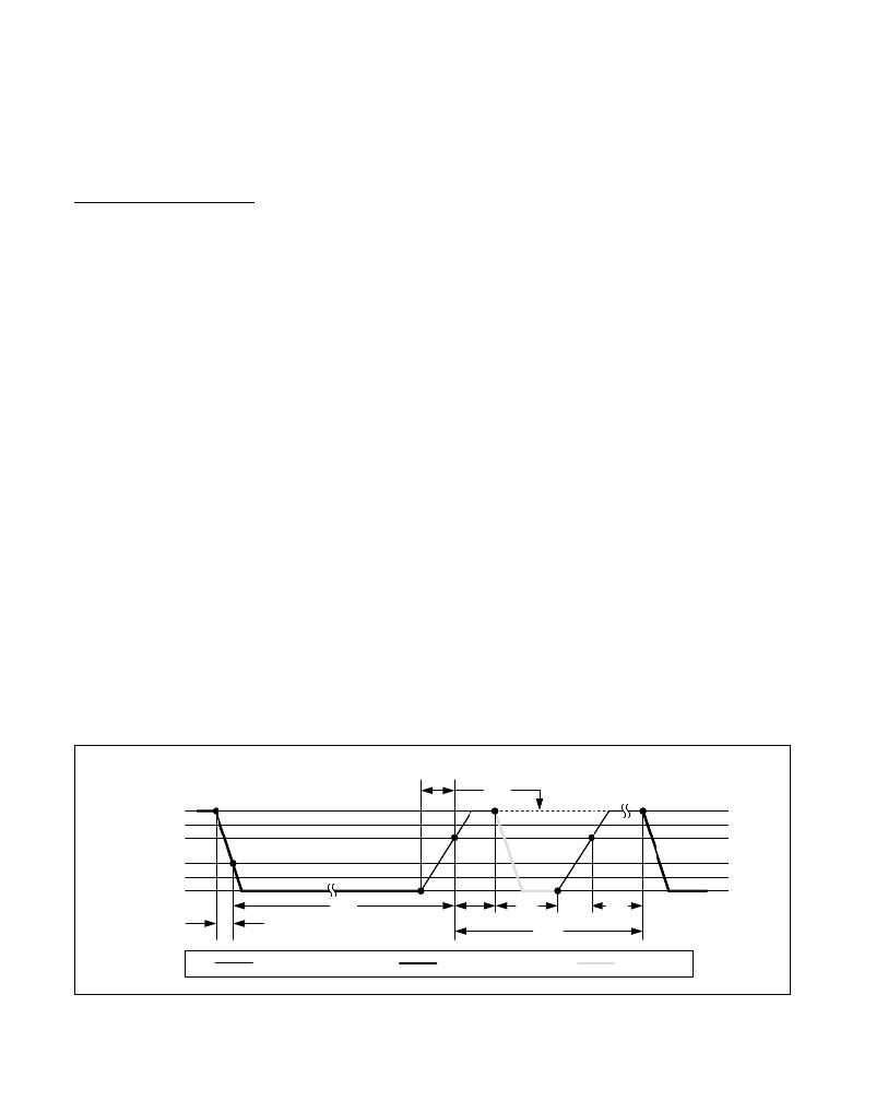
�voltage� to� make� this� rise� is� seen� in� Figure� 10� as� ε� ,� and�
�its� duration� depends� on� the� pullup� resistor� (R� PUP� )� used�
�and� the� capacitance� of� the� 1-Wire� network� attached.�
�The� voltage� V� ILMAX� is� relevant� for� the� DS24B33� when�
�determining� a� logical� level,� not� triggering� any� events.�
�Figure� 10� shows� the� initialization� sequence� required� to�
�begin� any� communication� with� the� DS24B33.� A� reset�
�pulse� followed� by� a� presence� pulse� indicates� that� the�
�DS24B33� is� ready� to� receive� data,� given� the� correct�
�ROM� and� memory� function� command.� If� the� bus� master�
�uses� slew-rate� control� on� the� falling� edge,� it� must� pull�
�down� the� line� for� t� RSTL� +� t� F� to� compensate� for� the� edge.�
�A� t� RSTL� duration� of� 480μs� or� longer� exits� the� overdrive�
�mode,� returning� the� device� to� standard� speed.� If� the�
�DS24B33� is� in� overdrive� mode� and� t� RSTL� is� no� longer�
�than� 80μs,� the� device� remains� in� overdrive� mode.� If� the�
�device� is� in� overdrive� mode� and� t� RSTL� is� between� 80μs�
�and� 480μs,� the� device� resets,� but� the� communication�
�speed� is� undetermined.�
�MASTER� Tx� "RESET� PULSE"�
�V� PUP�
�V� IHMASTER�
�V� TH�
�V� TL�
�V� ILMAX�
�ε�
�After� the� bus� master� has� released� the� line� it� goes� into�
�receive� mode.� Now� the� 1-Wire� bus� is� pulled� to� V� PUP�
�through� the� pullup� resistor,� or� in� case� of� a� DS2482-x00�
�or� DS2480B� driver,� by� active� circuitry.� When� the� thresh-�
�old� V� TH� is� crossed,� the� DS24B33� waits� for� t� PDH� and�
�then� transmits� a� presence� pulse� by� pulling� the� line� low�
�for� t� PDL� .� To� detect� a� presence� pulse,� the� master� must�
�test� the� logical� state� of� the� 1-Wire� line� at� t� MSP� .�
�The� t� RSTH� window� must� be� at� least� the� sum� of� t� PDHMAX� ,�
�t� PDLMAX� ,� and� t� RECMIN� .� Immediately� after� t� RSTH� is�
�expired,� the� DS24B33� is� ready� for� data� communication.�
�In� a� mixed� population� network,� t� RSTH� should� be� extend-�
�ed� to� minimum� 480μs� at� standard� speed� and� 48μs� at�
�overdrive� speed� to� accommodate� other� 1-Wire� devices.�
�Read/Write� Time� Slots�
�Data� communication� with� the� DS24B33� takes� place� in�
�time� slots,� which� carry� a� single� bit� each.� Write� time� slots�
�transport� data� from� bus� master� to� slave.� Read� time�
�slots� transfer� data� from� slave� to� master.� Figure� 11� illus-�
�trates� the� definitions� of� the� write� and� read� time� slots.�
�All� communication� begins� with� the� master� pulling� the�
�data� line� low.� As� the� voltage� on� the� 1-Wire� line� falls�
�below� the� threshold� V� TL� ,� the� DS24B33� starts� its� internal�
�timing� generator� that� determines� when� the� data� line� is�
�sampled� during� a� write� time� slot� and� how� long� data� is�
�valid� during� a� read� time� slot.�
�Master-to-Slave�
�For� a� write-one� time� slot,� the� voltage� on� the� data� line�
�must� have� crossed� the� V� TH� threshold� before� the� write-�
�one� low� time� t� W1LMAX� is� expired.� For� a� write-zero� time�
�slot,� the� voltage� on� the� data� line� must� stay� below� the�
�V� TH� threshold� until� the� write-zero� low� time� t� W0LMIN� is�
�expired.� For� the� most� reliable� communication,� the�
�MASTER� Rx� "PRESENCE� PULSE"�
�t� MSP�
�0V�
�t� RSTL�
�t� PDH�
�t� PDL�
�t� REC�
�t� F�
�t� RSTH�
�RESISTOR�
�Figure� 10.� Initialization� Procedure:� Reset� and� Presence� Pulse�
�Maxim� Integrated�
�MASTER�
�DS24B33�
�17�
�相关PDF资料 |
PDF描述 |
|---|---|
| 10326-A200-00 | CONN JUNCTION SHELL 26POS STRGT |
| EP1AGX20CF484I6N | IC ARRIA GX FPGA 20K 484FBGA |
| A54SX72A-PQG208A | IC FPGA SX-A 108K 208-PQFP |
| A54SX72A-PQ208A | IC FPGA SX-A 108K 208-PQFP |
| GBB95DHBR | CONN EDGECARD 190PS R/A .050 SLD |
相关代理商/技术参数 |
参数描述 |
|---|---|
| DS24B33S R | 制造商:MAXIM 制造商全称:Maxim Integrated Products 功能描述:1-Wire 4Kb EEPROM |
| DS24B33S T | 制造商:MAXIM 制造商全称:Maxim Integrated Products 功能描述:1-Wire 4Kb EEPROM |
| DS24B33S TR | 制造商:MAXIM 制造商全称:Maxim Integrated Products 功能描述:1-Wire 4Kb EEPROM |
| DS24B33S+ | 功能描述:电可擦除可编程只读存储器 1-Wire 4kbit 电可擦除可编程只读存储器 RoHS:否 制造商:Atmel 存储容量:2 Kbit 组织:256 B x 8 数据保留:100 yr 最大时钟频率:1000 KHz 最大工作电流:6 uA 工作电源电压:1.7 V to 5.5 V 最大工作温度:+ 85 C 安装风格:SMD/SMT 封装 / 箱体:SOIC-8 |
| DS24B33S+R | 制造商:MAXIM 制造商全称:Maxim Integrated Products 功能描述:4Kb 1-Wire EEPROM with 200k Write/Erase Cycles |
发布紧急采购,3分钟左右您将得到回复。