- 您现在的位置:买卖IC网 > PDF目录1916 > DS8007A-EAG+ (Maxim Integrated Products)IC INTERFACE SMART CARD 48-LQFP PDF资料下载
参数资料
| 型号: | DS8007A-EAG+ |
| 厂商: | Maxim Integrated Products |
| 文件页数: | 24/41页 |
| 文件大小: | 0K |
| 描述: | IC INTERFACE SMART CARD 48-LQFP |
| 产品培训模块: | Lead (SnPb) Finish for COTS Obsolescence Mitigation Program |
| 标准包装: | 104 |
| 应用: | 智能卡 |
| 接口: | 并联 |
| 电源电压: | 2.7 V ~ 6 V |
| 封装/外壳: | 48-LQFP |
| 供应商设备封装: | 48-LQFP(7x7) |
| 包装: | 管件 |
| 安装类型: | 表面贴装 |
第1页第2页第3页第4页第5页第6页第7页第8页第9页第10页第11页第12页第13页第14页第15页第16页第17页第18页第19页第20页第21页第22页第23页当前第24页第25页第26页第27页第28页第29页第30页第31页第32页第33页第34页第35页第36页第37页第38页第39页第40页第41页
DS8007A
Multiprotocol Dual Smart Card Interface
30
______________________________________________________________________________________
Timeout Counter Operation
The timeout counter assists the host device in timing
real-time events associated with the communication pro-
tocols: the Work Wait Time (WWT), Block Waiting Time
(BWT), etc. The timeout counter registers count ETUs, so
the input clock to the timeout counter is derived from the
output of the programmable divided clock (per card PDR
register). The timeout counter requires the card be pow-
ered and have an active clock.
The timeout counter can operate as a single 24-bit
counter (TOR3–TOR1) or as separate 16-bit
(TOR3–TOR2) and 8-bit (TOR1) counters. The timeout
counters can be operated in either software mode or
start bit mode. The software mode is supported for the
16-bit and 24-bit counters. The start-bit mode is sup-
ported for all counter widths (8 bit, 16 bit, and 24 bit).
See Table 3.
Software Mode
In software mode, software configures the counter to a
starting value (while stopped) and starts the down
counter by writing the configuration value to the TOC
register. When the terminal count is reached (0h), the
counter stops, the timeout flag is set, and an interrupt is
generated. If the software counter does not reach the
terminal count, it must be stopped before loading a
new value into the associated TORx counter registers.
It is possible to stop and start the 16-bit software
counter while leaving the 8-bit counter enabled (e.g.,
TOC = 65h
05h, TOC = E5h 85h, etc.).
If a compatible software mode command is written to the
TOC register before the terminal count is reached (e.g.,
write 61h to TOC register while the 65h TOC command is
running or vice versa), the new command is ignored (still
software mode), but the TOC register is updated with the
new command, and the counter continues to count until
the terminal count is reached, the respective timeout
flag(s) is set, and an interrupt is generated.
Start-Bit Mode
When configured to start-bit mode, counting starts (and
restarts for the 16-bit and 24-bit counters) when a
START bit is detected on the active card interface I/Ox
pin. When the terminal count is reached, the 8-bit
autoreload counter begins counting from the previously
programmed start value, while a 16-bit counter or 24-bit
counter stops when terminal count is reached. If the
terminal count is reached, the timeout flag is set and an
interrupt is generated. The 8-bit autoreload TOR1 regis-
ter cannot be modified during a count. The 16-bit and
24-bit counter registers can be modified during a count
without affecting the current count. The new register
data is used on the next START bit detection.
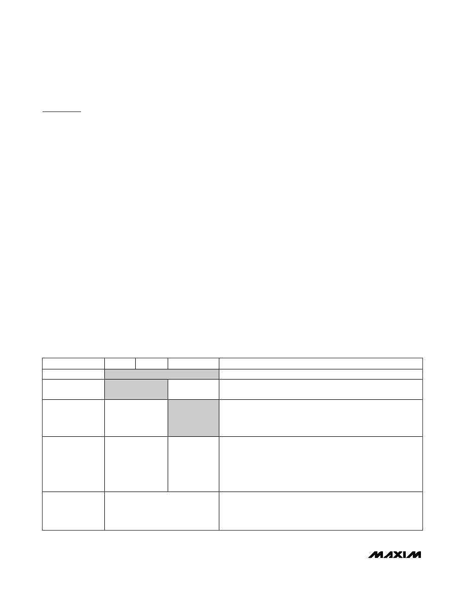
Table 3. Timeout Counter Configurations
TOC VALUE
TOR3
TOR2
TOR1
DESCRIPTION
00h
Stopped
All counters are stopped.
05h
Stopped
Start
Bit/Autoreload
Counters 3 and 2 are stopped. Counter 1 continues in start-
bit/autoreload mode for both transmission and reception.
61h
Software
Stopped
Counter 1 is stopped. Counters 3 and 2 form a 16-bit counter
operating in software mode. The counter is stopped by writing 00h
to the TOC register, and must be stopped before reloading new
values in TOR3 and TOR2 registers.
65h
Software
Start
Bit/Autoreload
Counters 3 and 2 form a 16-bit counter operating in software mode.
Writing 05h to the TOC register before reloading new values in
TOR2/TOR3 stops the counters. Counter 1 is operated in start-
bit/autoreload mode. The TOR1 register may not change during the
count. The 16-bit counters are stopped by setting TOC = 05h. Both
counters are stopped by setting TOC = 00h.
68h
Software
Counters 1, 2, and 3 form a 24-bit counter operating in software
mode. The counter starts after the command is written to the TOC
register, and is stopped by setting TOC = 00h. TOR3, TOR2, TOR1
cannot be changed without stopping the counter first.
相关PDF资料 |
PDF描述 |
|---|---|
| DS8023-RRX+ | IC INTERFACE SMART CARD 28-SOIC |
| DS80C310-ECG | IC MCU HI SPEED 25MHZ 44-TQFP |
| DS80C320-ECL/T&R | IC MCU HI SPEED 33MHZ 44-TQFP |
| DS80C390-FNR | IC MPU CAN DUAL HS IND 64-LQFP |
| DS80C400-FNY | IC MCU 75MHZ 16MB HP 100-LQFP |
相关代理商/技术参数 |
参数描述 |
|---|---|
| DS8007A-EAG+ | 功能描述:接口 - 专用 Multiprotocol Dual Smart Card Interface RoHS:否 制造商:Texas Instruments 产品类型:1080p60 Image Sensor Receiver 工作电源电压:1.8 V 电源电流:89 mA 最大功率耗散: 最大工作温度:+ 85 C 安装风格:SMD/SMT 封装 / 箱体:BGA-59 |
| DS8007A-EAG+T | 功能描述:接口 - 专用 Multiprotocol Dual Smart Card Interface RoHS:否 制造商:Texas Instruments 产品类型:1080p60 Image Sensor Receiver 工作电源电压:1.8 V 电源电流:89 mA 最大功率耗散: 最大工作温度:+ 85 C 安装风格:SMD/SMT 封装 / 箱体:BGA-59 |
| DS8007-ENG | 制造商:DALLAS 制造商全称:Dallas Semiconductor 功能描述:Multiprotocol Dual Smart Card Interface |
| DS8007-ENG+ | 功能描述:接口 - 专用 Multiprotocol Dual Smart Card Interface RoHS:否 制造商:Texas Instruments 产品类型:1080p60 Image Sensor Receiver 工作电源电压:1.8 V 电源电流:89 mA 最大功率耗散: 最大工作温度:+ 85 C 安装风格:SMD/SMT 封装 / 箱体:BGA-59 |
| DS8007-KIT | 功能描述:界面开发工具 DS8007 Eval Kit RoHS:否 制造商:Bourns 产品:Evaluation Boards 类型:RS-485 工具用于评估:ADM3485E 接口类型:RS-485 工作电源电压:3.3 V |
发布紧急采购,3分钟左右您将得到回复。