- 您现在的位置:买卖IC网 > PDF目录97873 > E720-EDGE720 500 MHz Pin Electronics Driver. Window Comparator. and Load PDF资料下载
参数资料
| 型号: | E720-EDGE720 |
| 英文描述: | 500 MHz Pin Electronics Driver. Window Comparator. and Load |
| 中文描述: | 500兆赫引脚电子驱动器。窗口比较器。和负载 |
| 文件页数: | 3/31页 |
| 文件大小: | 221K |
| 代理商: | E720-EDGE720 |
第1页第2页当前第3页第4页第5页第6页第7页第8页第9页第10页第11页第12页第13页第14页第15页第16页第17页第18页第19页第20页第21页第22页第23页第24页第25页第26页第27页第28页第29页第30页第31页
11
www .semtech.com
TEST AND MEASUREMENT PRODUCTS
Edge720
Revision 4 / September 24, 2002
Circuit Description (continued)
Load Circuit Description
Introduction
The Edge720 features a programmable load circuit which
is capable of sourcing or sinking up to 35 mA over a –1V
to +12V range, or being placed in a high impedance state.
This circuit also features “split” commutating voltage inputs
that allow it to be configured as a programmable voltage
clamp. In addition, the BRIDGE_SC and BRIDGE_SK pins
allow the load circuit’s diode bridge to be connected to
external current sources for increased low current accuracy.
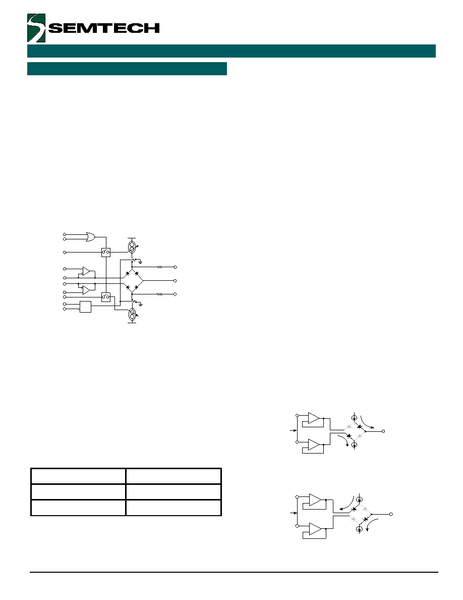
A functional schematic of the Edge720’s load circuit can
be seen below in Figure 12.
Figure 12. Functional Schematic of the
Edge720’s Load Circuit
Load Enable
The Edge720 load circuit features a differential “Flex In”
input labeled LD_EN(*). This input can be used to isolate
the diode bridge from the on-chip current supplies, leaving
the LOAD pin in a high impedance state. “Flex In” inputs
are wide voltage inputs which allow the LD_EN(*) pin to
be used with ECL, TTL, CMOS, or custom level inputs, and
whose characteristics are described in Table 1. LD_EN(*)
functionality is described in Table 6.
Table 6. Load Enable Input Functionality
Single-ended operation can be attained by connecting the
inverting input, LD_EN* to the desired DC threshold level.
t
u
p
n
I
e
l
b
a
n
E
d
a
o
Ln
o
it
a
r
e
p
O
*
N
E
_
D
L
<
N
E
_
D
Le
c
n
a
d
e
p
m
I
h
g
i
H
*
N
E
_
D
L
>
N
E
_
D
Le
v
i
t
c
A
Current Programming Inputs
ISC_IN and ISK_IN are independently adjustable analog
current inputs that control the amount of current being
supplied to the diode bridge by the on-chip current supplies
(see Figure 12). Consequently, these inputs can be used
to program the amount of current being sourced (ISC_IN)
or sunk (ISK_IN) at the load circuit output pin (LOAD).
The on-chip current supplies have been designed to have
a nominal gain of 20. Therefore, the magnitude of current
sourced or sunk is equal to the magnitude of the control
current scaled by a factor of 20. The ISK_IN and ISC_IN
current programming inputs should be routed on a PCB
such that coupling between the control inputs and the
LOAD, VCM_OUT_A and VCM_OUT_B pins is minimized.
Finally, it is also recommended that 1 k
of external series
resistance be connected between these inputs and the
source controlling them. A group E DAC on the Edge6420
offers a nice solution to controlling these inputs.
Commutating Voltage Inputs
VCM_IN_A(B) are high impedance analog voltage inputs
to on-chip buffers that are used to set the voltage level at
which the diode bridge switches from sourcing to sinking
current when the load is connected as a standard active
load (see Figure 15).
If the voltages applied to
VCM_IN_A(B) are more positive than that on the LOAD
pin, the bridge will source current from the LOAD pin (see
Figure 13). If the voltage applied to VCM_IN_A(B) is less
than that at the LOAD pin, the bridge will sink current
through the LOAD pin (see Figure 14).
Figure 13. Edge720 Load Circuit Sources Current
Figure 14. Edge720 Load Circuit Sinks Current
ISC_IN
IPD_C
SUPERV
VCM_IN_A
VCM_IN_B
VCM_OUT_A
VCM_OUT_B
ISK_IN
LD_EN
LD_EN*
LOAD
BRIDGE_SC
BRIDGE_SK
VCC
VEE
1 K
1 K
ISC
ISK
VCM_IN_A
LOAD
VCM_IN_B
External
Connection
VCM_IN_A(B) > LOAD
VCM_IN_A
LOAD
VCM_IN_B
External
Connection
VCM_IN_A(B) < LOAD
相关PDF资料 |
PDF描述 |
|---|---|
| E728-EDGE728 | Very High-Speed Dual- and Quad-Channel ECL Delay Lines |
| E737-EDGE737 | Per-Pin Precision Measurement Unit |
| E749-EDGE749 | Octal Pin Electronics Driver / Receiver |
| E818-EDGE818 | Octal 18 V Pin Electronics Driver / Window Comparator |
| E819-EDGE819 | Octal 18 V Pin Electronics Driver |
相关代理商/技术参数 |
参数描述 |
|---|---|
| E72106-000 | 制造商:TE Connectivity 功能描述:DWP-125-1/2-0-80MM - Bulk |
| E72-12V | 制造商:GILWAY 制造商全称:Gilway Technical Lamp 功能描述:Engineering Catalog 169 |
| E722455 | 制造商:Elo Touch Solutions Inc 功能描述:1520 TOUCHCOMPUTER - 15-INCH LCD, ACCUTOUCH (RESISTIVE), USB - Bulk |
| E72246-000 | 功能描述:可复位保险丝 250V .08A-HD 3A MAX (R) RoHS:否 制造商:Bourns 电流额定值: 电阻:7.5 Ohms 最大直流电压: 保持电流:0.1 A 安装风格:SMD/SMT 端接类型:SMD/SMT 跳闸电流:0.6 A 引线间隔: 系列:MF-PSHT 工作温度范围:- 40 C to + 125 C |
| E72382-000 | 制造商:TE Connectivity 功能描述:MTCPQKT2P22SGBD |
发布紧急采购,3分钟左右您将得到回复。