参数资料
| 型号: | EL1517AIYE-T13 |
| 厂商: | Intersil |
| 文件页数: | 10/10页 |
| 文件大小: | 0K |
| 描述: | IC LINE DRIVER XDSL DIFF 10-MSOP |
| 标准包装: | 2,500 |
| 类型: | 驱动器 |
| 驱动器/接收器数: | 1/0 |
| 规程: | DSL |
| 电源电压: | 5 V ~ 12 V |
| 安装类型: | 表面贴装 |
| 封装/外壳: | 10-VFSOP,10-MSOP(0.118",3.00mm 宽)裸露焊盘 |
| 供应商设备封装: | 10-HMSOP |
| 包装: | 带卷 (TR) |
9
FN6139.2
August 8, 2006
Applications Information
Product Description
The EL1517A is a dual operational amplifier designed for
line driving in DMT ADSL and VDSL solutions. It is a dual
current mode feedback amplifier with low distortion while
drawing moderately low supply current. It is built using
Elantec’s proprietary complimentary bipolar process and is
offered in industry standard pinouts. Due to the current
feedback architecture, the EL1517A closed-loop 3dB
bandwidth is dependent on the value of the feedback
resistor. First the desired bandwidth is selected by choosing
the feedback resistor, RF, and then the gain is set by picking
the gain resistor, RG. The curves at the beginning of the
Typical Performance Curves section show the effect of
varying both RF and RG. The 3dB bandwidth is somewhat
dependent on the power supply voltage.
Power Supply Bypassing and Printed Circuit
Board Layout
As with any high frequency device, good printed circuit
board layout is necessary for optimum performance. Ground
plane construction is highly recommended. Lead lengths
should be as short as possible, below ”. The power supply
pins must be well bypassed to reduce the risk of oscillation.
A 4.7F tantalum capacitor in parallel with a 0.1F ceramic
capacitor is adequate for each supply pin.
For good AC performance, parasitic capacitances should be
kept to a minimum, especially at the inverting input. This
implies keeping the ground plane away from this pin. Carbon
resistors are acceptable, while use of wire-wound resistors
should not be used because of their parasitic inductance.
Similarly, capacitors should be low inductance for best
performance.
Capacitance at the Inverting Input
Due to the topology of the current feedback amplifier, stray
capacitance at the inverting input will affect the AC and
transient performance of the EL1517A when operating in the
non-inverting configuration.
In the inverting gain mode, added capacitance at the
inverting input has little effect since this point is at a virtual
ground and stray capacitance is therefore not “seen” by the
amplifier.
Feedback Resistor Values
The EL1517A has been designed and specified with
RF = 750 for AV = +5. This value of feedback resistor yields
extremely flat frequency response with little to no peaking
out to 200MHz. As is the case with all current feedback
amplifiers, wider bandwidth, at the expense of slight
peaking, can be obtained by reducing the value of the
feedback resistor. Inversely, larger values of feedback
resistor will cause rolloff to occur at a lower frequency. See
the curves in the Typical Performance Curves section which
show 3dB bandwidth and peaking vs. frequency for various
feedback resistors and various supply voltages.
Bandwidth vs Temperature
Whereas many amplifier's supply current and consequently
3dB bandwidth drop off at high temperature, the EL1517A
was designed to have little supply current variations with
temperature. An immediate benefit from this is that the 3dB
bandwidth does not drop off drastically with temperature.
Supply Voltage Range
The EL1517A has been designed to operate with single
supply voltages from +5V to +12V nominal. When using a
single supply, be sure to either 1) DC bias the inputs at an
appropriate common mode voltage and AC couple the
signal, or 2) ensure the driving signal is within the common
mode range of the EL1517A. Optimum bandwidth, slew rate,
and video characteristics are obtained at higher supply
voltages. However, at +5V supplies, the 3dB bandwidth at
AV = +5 is a respectable 200MHz. The EL1517A cannot be
used in dual supply configurations. Use EL1517IL or
EL1517IS for dual supply applications.
ADSL CPE Applications
The EL1517A is designed as a line driver for ADSL CPE
modems. It is capable of outputting 450mA of output current
with a typical supply voltage headroom of 1.3V. It can
achieve -85dBc of distortion at low 7.1mA of supply current
per amplifier.
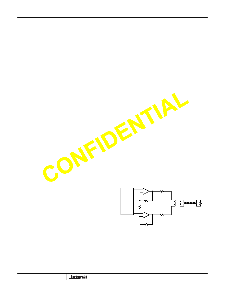
The average line power requirement for the ADSL CPE
application is 13dBm (20mW) into a 100
line. The average
line voltage is 1.41VRMS. The ADSL DMT peak to average
ratio (crest factor) of 5.3 implies peak voltage of 7.5V into the
line. Using a differential drive configuration and transformer
coupling with standard back termination, a transformer ratio
of 1:2 is selected. The circuit configuration is as shown
below.
-
+
-
+
TX1
1:2
12.5
750
250
AFE
100
EL1517A
相关PDF资料 |
PDF描述 |
|---|---|
| EL1517AIYE | IC LINE DRIVER XDSL DIFF 10-MSOP |
| MS3452L20-4PY | CONN RCPT 4POS BOX MNT W/PINS |
| MS27467E25F43SB | CONN PLUG 43POS STRAIGHT W/SCKT |
| MS3452L20-4PX | CONN RCPT 4POS BOX MNT W/PINS |
| EL1517ISZ-T13 | IC LINE DRIVER XDSL DIFF 8-SOIC |
相关代理商/技术参数 |
参数描述 |
|---|---|
| EL1517AIYE-T7 | 功能描述:IC LINE DRIVER XDSL DIFF 10-MSOP RoHS:否 类别:集成电路 (IC) >> 接口 - 驱动器,接收器,收发器 系列:- 标准包装:1,000 系列:- 类型:收发器 驱动器/接收器数:2/2 规程:RS232 电源电压:3 V ~ 5.5 V 安装类型:表面贴装 封装/外壳:16-SOIC(0.295",7.50mm 宽) 供应商设备封装:16-SOIC 包装:带卷 (TR) |
| EL1517AIYEZ | 制造商:INTERSIL 制造商全称:Intersil Corporation 功能描述:xDSL Differential Line Driver |
| EL1517AIYEZ-T13 | 制造商:INTERSIL 制造商全称:Intersil Corporation 功能描述:xDSL Differential Line Driver |
| EL1517AIYEZ-T7 | 制造商:INTERSIL 制造商全称:Intersil Corporation 功能描述:xDSL Differential Line Driver |
| EL1517B | 制造商:INTERSIL 制造商全称:Intersil Corporation 功能描述:xDSL Differential Line Driver |
发布紧急采购,3分钟左右您将得到回复。