- 您现在的位置:买卖IC网 > PDF目录10560 > EL4511CU (Intersil)IC VID SYNC SEPARATR HDTV 24QSOP PDF资料下载
参数资料
| 型号: | EL4511CU |
| 厂商: | Intersil |
| 文件页数: | 17/24页 |
| 文件大小: | 0K |
| 描述: | IC VID SYNC SEPARATR HDTV 24QSOP |
| 标准包装: | 55 |
| 类型: | 同步分离器 |
| 应用: | HDTV,投影仪,机顶盒 |
| 安装类型: | 表面贴装 |
| 封装/外壳: | 24-SSOP(0.154",3.90mm 宽) |
| 供应商设备封装: | 24-QSOP |
| 包装: | 管件 |
24
All Intersil U.S. products are manufactured, assembled and tested utilizing ISO9000 quality systems.
Intersil Corporation’s quality certifications can be viewed at www.intersil.com/design/quality
Intersil products are sold by description only. Intersil Corporation reserves the right to make changes in circuit design, software and/or specifications at any time without
notice. Accordingly, the reader is cautioned to verify that data sheets are current before placing orders. Information furnished by Intersil is believed to be accurate and
reliable. However, no responsibility is assumed by Intersil or its subsidiaries for its use; nor for any infringements of patents or other rights of third parties which may result
from its use. No license is granted by implication or otherwise under any patent or patent rights of Intersil or its subsidiaries.
For information regarding Intersil Corporation and its products, see www.intersil.com
FN7009.8
November 12, 2010
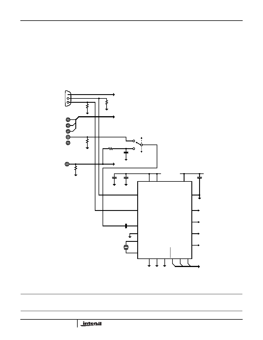
Application 3 (application using a microcontroller
interface)
In this example, the requirement is to provide the
synchronizing information in a video digitizing interface. This
example is very similar to the example in application 2. In
this example the incoming sync signals may come from one
of three sources. Computer, HDTV source or an NTSC/PAL
device.
As there is a Microcontroller connected in this example, a
32.768kHz XTAL is connected to pins 1 & 24; this will allow
the system microcontroller to gather timing information for
the vertical rate. To enable the crystal oscillator, register 9,
bit 6 must be set to a high.
Note that a Low Pass Filter is in the NTSC/PAL signal path to
reduce noise, glitches and subcarrier. (In signals with bad
Croma/Luma gain balance, the subcarrier can extend into
the sync slicing level).
As some of the signals in this application were non standard
formats, the fixed slice mode is used by setting register 2,
bit 5 to a high. Register 1, bit 6 is also set to a high. This
forced the EL4511 to provide outputs even when the input
signals are not recognized by the internal algorithms.
FIGURE 12. APPLICATIONS DRAWING 3
9
XTALN
11
10
4
1
24
XTAL
PDWN
SYNCIN
VERTIN
HIN
8
GNDD1
13
GNDA2
17
GNDD2
6
SCL
7
SDA
14
18
15
V
CCA1
VCCD
V
CCA2
16
+
22
21
GNDA2
VERTOUT
HOUT
4.7F
0.1F
100nF
VCC
0.1F
VERTICAL
TIMING
HORIZONTAL
TIMING
EL4511
VIDEO SIGNAL (CVBS)
VIDEO SIGNALS (HDTV)
VIDEO SIGNALS (RGB)
H SYNC
V SYNC
HDTV
SYNCS
CVBS
75
Ω
75
Ω
75
Ω
75
Ω
620
Ω
510pF
COMPONENT
COMPOSITE
SDENB
5
TO MICROCONTROLLER
20
2
BACKPORCH
VBLANK
VIDEO
CLAMP
PLL
COAST
32.768kHz
CRYSTAL
EL4511
相关PDF资料 |
PDF描述 |
|---|---|
| EL1883IS | IC VIDEO SYNC SEPARATOR 8-SOIC |
| VI-J1Z-MX-F3 | CONVERTER MOD DC/DC 2V 30W |
| MS3102A20-21P | CONN RCPT 9POS BOX MNT W/PINS |
| VE-25Y-IU-F1 | CONVERTER MOD DC/DC 3.3V 132W |
| VI-J0J-MY-F3 | CONVERTER MOD DC/DC 36V 50W |
相关代理商/技术参数 |
参数描述 |
|---|---|
| EL4511CU-T13 | 功能描述:IC SUPER SYNC SEPARATOR 24-QSOP RoHS:否 类别:集成电路 (IC) >> 线性 - 视频处理 系列:- 产品变化通告:Product Discontinuation 07/Mar/2011 标准包装:3,000 系列:OMNITUNE™ 类型:调谐器 应用:移动电话,手机,视频显示器 安装类型:表面贴装 封装/外壳:65-WFBGA 供应商设备封装:PG-WFSGA-65 包装:带卷 (TR) 其它名称:SP000365064 |
| EL4511CU-T7 | 功能描述:IC VID SYNC SEPARATR HDTV 24QSOP RoHS:否 类别:集成电路 (IC) >> 线性 - 视频处理 系列:- 产品变化通告:Product Discontinuation 07/Mar/2011 标准包装:3,000 系列:OMNITUNE™ 类型:调谐器 应用:移动电话,手机,视频显示器 安装类型:表面贴装 封装/外壳:65-WFBGA 供应商设备封装:PG-WFSGA-65 包装:带卷 (TR) 其它名称:SP000365064 |
| EL4511CUZ | 功能描述:视频 IC EL4511CUZ SUPER SYNC SEPARATOR RoHS:否 制造商:Fairchild Semiconductor 工作电源电压:5 V 电源电流:80 mA 最大工作温度:+ 85 C 封装 / 箱体:TSSOP-28 封装:Reel |
| EL4511CUZ | 制造商:Intersil Corporation 功能描述:TV / Video IC |
| EL4511CUZ-EVAL | 制造商:Intersil Corporation 功能描述:SUPER SYNC SEPARATOR 24QSOP - Bulk |
发布紧急采购,3分钟左右您将得到回复。