参数资料
| 型号: | EL7586AILZ-T13 |
| 厂商: | Intersil |
| 文件页数: | 12/21页 |
| 文件大小: | 0K |
| 描述: | IC POWER SUPPLY TFT-LCD 20-QFN |
| 标准包装: | 2,500 |
| 应用: | 转换器,TFT,LCD |
| 输入电压: | 3 V ~ 5 V |
| 输出数: | 4 |
| 输出电压: | 5.5 V ~ 20 V |
| 工作温度: | -40°C ~ 85°C |
| 安装类型: | 表面贴装 |
| 封装/外壳: | 20-VFQFN 裸露焊盘 |
| 供应商设备封装: | 20-QFN 裸露焊盘(4x4) |
| 包装: | 带卷 (TR) |
�� �
�
�EL7586,� EL7586A�
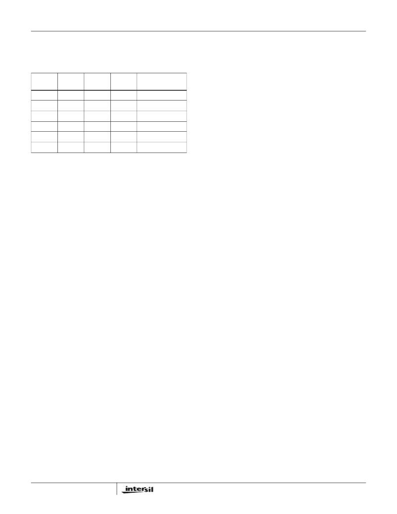
�The� following� table� gives� typical� values� (margins� are�
�considered� 10%,� 3%,� 20%,� 10%,� and� 15%� on� V� IN� ,� V� O� ,� L,� f� S� ,�
�and� I� OMAX� :�
�capacitor.� The� voltage� rating� of� the� output� capacitor� should�
�be� greater� than� the� maximum� output� voltage.�
�NOTE:� Capacitors� have� a� voltage� coefficient� that� makes� their�
�V� IN� (V)�
�V� O� (V)�
�TABLE� 2.�
�L� (� μH)� (MHz)�
�f� S�
�I� OMAX�
�(EL7586,� EL7586A)�
�effective� capacitance� drop� as� the� voltage� across� them� increases.�
�C� OUT� in� the� equation� above� assumes� the� effective� value� of� the�
�capacitor� at� a� particular� voltage� and� not� the� manufacturer� ’s� stated�
�value,� measured� at� zero� volts.�
�3.3�
�3.3�
�3.3�
�5�
�5�
�5�
�9�
�12�
�15�
�9�
�12�
�15�
�6.8�
�6.8�
�6.8�
�6.8�
�6.8�
�6.8�
�1�
�1�
�1�
�1�
�1�
�1�
�0.490686�
�0.307353�
�0.197353�
�0.743464�
�0.465686�
�0.29902�
�Compensation�
�The� EL7586,� and� EL7586A� can� operate� in� either� P� mode� or�
�PI� mode.� Connecting� the� C� INT� pin� directly� to� V� IN� will� enable�
�P� mode;� For� better� load� regulation,� use� PI� mode� with� a�
�4.7nF� capacitor� in� series� with� a� 10K� resistor� between� C� INT�
�and� ground.� This� value� may� be� reduced� to� improve� transient�
�performance,� however,� very� low� values� will� reduce� loop�
�stability.�
�I� LAVG� =� -------------�
�I� LPK� =� I� LAVG� +� --------� L�
�V� RIPPLE� =� I� LPK� � ESR� +� ------------------------� � ----------------� � -----�
�Input� Capacitor�
�An� input� capacitor� is� used� to� supply� the� peak� charging�
�current� to� the� converter.� It� is� recommended� that� C� IN� be�
�larger� than� 10μF.� The� reflected� ripple� voltage� will� be� smaller�
�with� larger� C� IN� .� The� voltage� rating� of� input� capacitor� should�
�be� larger� than� maximum� input� voltage.�
�Boost� Inductor�
�The� boost� inductor� is� a� critical� part� which� influences� the�
�output� voltage� ripple,� transient� response,� and� efficiency.�
�Values� of� 3.3μH� to� 10μH� are� to� match� the� internal� slope�
�compensation.� The� inductor� must� be� able� to� handle� the�
�following� average� and� peak� current:�
�I� O�
�1� –� D�
�?� I�
�2�
�Rectifier� Diode�
�A� high-speed� diode� is� necessary� due� to� the� high� switching�
�frequency.� Schottky� diodes� are� recommended� because� of�
�their� fast� recovery� time� and� low� forward� voltage.� The� rectifier�
�diode� must� meet� the� output� current� and� peak� inductor�
�current� requirements.�
�Output� Capacitor�
�The� output� capacitor� supplies� the� load� directly� and� reduces�
�the� ripple� voltage� at� the� output.� Output� ripple� voltage�
�consists� of� two� components:� the� voltage� drop� due� to� the�
�inductor� ripple� current� flowing� through� the� ESR� of� output�
�capacitor,� and� the� charging� and� discharging� of� the� output�
�capacitor.�
�V� O� –� V� IN� I� O� 1�
�V� O� C� OUT� f� S�
�For� low� ESR� ceramic� capacitors,� the� output� ripple� is�
�dominated� by� the� charging� and� discharging� of� the� output�
�12�
�Boost� Feedback� Resistors�
�As� the� boost� output� voltage,� A� VDD� ,� is� reduced� below� 12V� the�
�effective� voltage� feedback� in� the� IC� increases� the� ratio� of�
�voltage� to� current� feedback� at� the� summing� comparator�
�because� R� 2� decreases� relative� to� R� 1� .� To� maintain� stable�
�operation� over� the� complete� current� range� of� the� IC,� the�
�voltage� feedback� to� the� FBB� pin� should� be� reduced�
�proportionally,� as� A� VDD� is� reduced,� by� means� of� a� series�
�resistor-capacitor� network� (R� 7� and� C� 7� )� in� parallel� with� R� 1� ,�
�with� a� pole� frequency� (f� p� )� set� to� approximately� 10kHz� for� C� 2�
�effective� =� 10μF� and� 4kHz� for� C� 2� (effective)� =� 30μF.�
�R� 7� =� ((1/0.1� x� R� 2� )� -� 1/R� 1� )^-1�
�C� 7� =� 1/(2� x� 3.142� x� f� p� x� R� 7� )�
�PI� Mode� C� INT� (C� 23� )� and� R� INT� (R� 10� )�
�The� IC� is� designed� to� operate� with� a� minimum� C� 23� capacitor�
�of� 4.7nF� and� a� minimum� C� 2� (effective)� =� 10μF.�
�Note� that,� for� high� voltage� A� VDD� ,� the� voltage� coefficient� of�
�ceramic� capacitors� (C� 2� )� reduces� their� effective� capacitance�
�greatly;� a� 16V� 10μF� ceramic� can� drop� to� around� 3μF� at� 15V.�
�To� improve� the� transient� load� response� of� A� VDD� in� PI� mode,�
�a� resistor� may� be� added� in� series� with� the� C� 23� capacitor.� The�
�larger� the� resistor� the� lower� the� overshoot� but� at� the� expense�
�of� stability� of� the� converter� loop� -� especially� at� high� currents.�
�With� L� =� 10μH,� A� VDD� =� 15V,� C� 23� =� 4.7nF,� C� 2� (effective)�
�should� have� a� capacitance� of� greater� than� 10μF.� R� INT� (R� 7� )�
�can� have� values� up� to� 5k� ?� for� C� 2� (effective)� up� to� 20μF� and�
�up� to� 10K� for� C� 2� (effective)� up� to� 30μF.�
�Larger� values� of� R� INT� (R� 7� )� may� be� possible� if� maximum�
�A� VDD� load� currents� less� than� the� current� limit� are� used.� To�
�ensure� A� VDD� stability,� the� IC� should� be� operated� at� the�
�maximum� desired� current� and� then� the� transient� load�
�response� of� A� VDD� should� be� used� to� determine� the�
�maximum� value� of� R� INT� .�
�FN9210.2�
�January� 17,� 2006�
�相关PDF资料 |
PDF描述 |
|---|---|
| 2510-24K | INDUCTOR RF 1.0UH UNSHIELDED SMD |
| ECA50DTMN | CONN EDGECARD 100PS R/A .125 SLD |
| 2510-22K | INDUCTOR RF .82UH UNSHIELDED SMD |
| 2510-20K | INDUCTOR RF .68UH UNSHIELDED SMD |
| ECA50DTMH | CONN EDGECARD 100PS R/A .125 SLD |
相关代理商/技术参数 |
参数描述 |
|---|---|
| EL7586AILZ-T7 | 功能描述:直流/直流开关调节器 EL7586AILZ TFT-LCD PWR SUPY RoHS:否 制造商:International Rectifier 最大输入电压:21 V 开关频率:1.5 MHz 输出电压:0.5 V to 0.86 V 输出电流:4 A 输出端数量: 最大工作温度: 安装风格:SMD/SMT 封装 / 箱体:PQFN 4 x 5 |
| EL7586ILZ | 功能描述:直流/直流开关调节器 EL7586ILZ TFT-LCD PWR SUPY RoHS:否 制造商:International Rectifier 最大输入电压:21 V 开关频率:1.5 MHz 输出电压:0.5 V to 0.86 V 输出电流:4 A 输出端数量: 最大工作温度: 安装风格:SMD/SMT 封装 / 箱体:PQFN 4 x 5 |
| EL7586ILZ-T13 | 功能描述:直流/直流开关调节器 EL7586ILZ TFT-LCD PWR SUPY RoHS:否 制造商:International Rectifier 最大输入电压:21 V 开关频率:1.5 MHz 输出电压:0.5 V to 0.86 V 输出电流:4 A 输出端数量: 最大工作温度: 安装风格:SMD/SMT 封装 / 箱体:PQFN 4 x 5 |
| EL7586ILZ-T7 | 功能描述:直流/直流开关调节器 EL7586ILZ TFT-LCD PWR SUPY RoHS:否 制造商:International Rectifier 最大输入电压:21 V 开关频率:1.5 MHz 输出电压:0.5 V to 0.86 V 输出电流:4 A 输出端数量: 最大工作温度: 安装风格:SMD/SMT 封装 / 箱体:PQFN 4 x 5 |
| EL7630 | 制造商:INTERSIL 制造商全称:Intersil Corporation 功能描述:White LED Boost Regulator |
发布紧急采购,3分钟左右您将得到回复。