- 您现在的位置:买卖IC网 > PDF目录97912 > ENH057Q1-450 Low Noise LDO with Low IQ, High PSRR; Temperature Range: -40°C to 85°C; Package: 6-uTDFN T&R PDF资料下载
参数资料
| 型号: | ENH057Q1-450 |
| 英文描述: | Low Noise LDO with Low IQ, High PSRR; Temperature Range: -40°C to 85°C; Package: 6-uTDFN T&R |
| 中文描述: | 5.7inch的QVGA |
| 文件页数: | 12/21页 |
| 文件大小: | 322K |
| 代理商: | ENH057Q1-450 |
Original specifications created by Sharp.
2
Panelview Hillsboro, OR (503) 690-2460
Panelview is a subsidiary of White Electronic Designs Corporation
ENH050Q1-320/450/600
Panelview
Enhancing the Vision
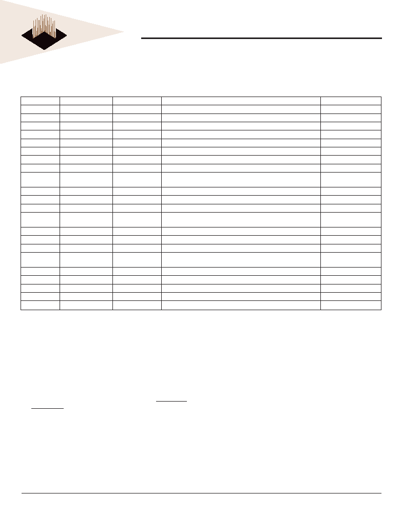
INPUT/OUTPUT TERMINALS AND THEIR DESCRIPTIONS
TFT-LCD PANEL DRIVING SECTION
(Hi means digital input voltage, Lo means GND.)
Pin No.
SymbolI/O
Description
Remarks
1
HSY
I, O
Input/output horizontal sync. signal (low active)
(1)
2
VSY
I, O
Input/output vertical sync. signal (low active)
(2)
3
PWM
O
Terminal for output PWM of dimming back light
(3)
4
NTP
I
Terminal for display mode change of NTSC and PAL
(4)
5
HRV
I
Turning the direction of horizontal scanning
(5)
6
VRV
I
Turning the direction of vertical scanning
(6)
7
VSW
I
Selection signal of two sets of video signals
(7)
8
SAM
I
Terminal for sampling mode change
(8)
9VCDC
I
DC bias voltage adjusting terminal of common
electrode driving signal
(9)
10
VSH
I
Positive power supply voltage
11
VBS
I
Composite video signal for sync. seperator
(10)
12
BRT
I
Brightness adjusting terminal
(11)
13
VR1
I
Color video signal (Red) 1
Positive
(On when VSW=Hi.)
14
VG1
I
Color video signal (Green) 1
↑
15
VB1
I
Color video signal (Blue) 1
↑
16
VSL
I
Negative power supply voltage
17
VR2
I
Color video signal (Red) 2
Positive
(On when VSW=Lo.)
18
VG2
I
Color video signal (Green) 2
↑
19
VB2
I
Color video signal (Blue) 2
↑
20
GND
I
Ground
21
CLKC
I
Change the input/output direction of CLK,HSY and VSY.
(12)
22
CLK
I, O
Input/output clock signal
(13)
Notes:
1. If CLKC=Hi, this terminal outputs horizontal sync. signal in phase with VBS.
If CLKC=Lo, this terminal will be external horizontal sync. input terminal.
2. If CLKC=Hi, this terminal outputs vertical sync. signal in phase with VBS.
If CLKC=Lo, this terminal will be external vertical sync. input terminal.
3. PWM signal is used for the PWM dimming frequency and it is easy to get PWM signal dimming by combining both HSY and PWM signal. But
use this PWM signal in case of input standard NTSC or PAL signal.
4. This terminal is to switch the display mode, and it is NTSC mode when NTP is High and is PAL mode when NTP is Low.
5. When this terminal is High, it will be normal and when it is Low, it will display reversely on the horizontal direction.
6. When this terminal is High, it will be normal and when it is Low, it will display reversely on the vertical direction.
7. This terminal is to switch input for groups of RGB color video signals, and Input 1 (No. 13 to 15) is selected when VSW is High and Input 2
(No. 17 to 19) is selected when VSW is Low.
8. This terminal switches the sampling mode. It is the independent data-sampling timing at RGB dots when SAM is High and it is the
simultaneous data-sampling timing at RGB dots when SAM is Low.
9. This terminal is applicable to the DC bias voltage adjusting terminal of the common electrode driving signal. If power supply voltage is typical, it
is not necessary to re-adjust it. So, use it in the open condition. However, in the case that the power supply voltage is changed, or power
supply voltage is reduced, adjust it externally to get the best contrast with a resistor that is added to this terminal, or semi-fixed
resistor, VCDC in module. A recommended circuit is shown in Fig. 5.
10. The sync. signal which will be input, is negative polarity and is applicable to standard composite sync. signal, negative one in the same pulse level.
11. DC voltage supplied to this terminal, makes the brightness of the screen adjustable, which is the black level of the video signal. Although this
is adjusted in the time of delivery to get the best display in the condition of the open terminal, it is also able to be re-adjusted externally with a
resistor that can be added to this terminal, or a semi-fixed resistor, BRT, in module. A recommended circuit is shown in Fig. 5.
12. CLKC=Hi, CLK.HSY.VSY terminals are output mode. CLKC= Lo : CLK. HSY. VSY terminals are input mode.
13. If CLKC=Hi, this terminal outputs the clock for source drivers. If CLKC=Lo, this terminal will be the external clock input terminal.
相关PDF资料 |
PDF描述 |
|---|---|
| ENH057Q1-600 | Low Noise LDO with Low IQ, High PSRR; Temperature Range: -40°C to 85°C; Package: 6-uTDFN T&R |
| ENH064V1-300 | Low Noise LDO with Low IQ, High PSRR; Temperature Range: -40°C to 85°C; Package: 6-uTDFN T&R |
| ENH064V1-450 | Low Noise LDO with Low IQ, High PSRR; Temperature Range: -40°C to 85°C; Package: 6-uTDFN T&R |
| ENH064V1-600 | 6.4inch VGA |
| ENH064V1-900 | LDO with Low ISUPPLY, High PSRR; Temperature Range: -40°C to 85°C; Package: 8-DFN T&R |
相关代理商/技术参数 |
参数描述 |
|---|---|
| ENH057Q1-600 | 制造商:未知厂家 制造商全称:未知厂家 功能描述:5.7inch QVGA |
| ENH057Q1-XXX | 制造商:WEDC 制造商全称:White Electronic Designs Corporation 功能描述:Color TFT-LCD Module Features GENERAL DESCRIPTION |
| ENH-0630 | 制造商:All American Ass'Y 功能描述: |
| ENH064V1-300 | 制造商:WEDC 制造商全称:White Electronic Designs Corporation 功能描述:Color TFT-LCD Module Features |
| ENH064V1-450 | 制造商:WEDC 制造商全称:White Electronic Designs Corporation 功能描述:Color TFT-LCD Module Features |
发布紧急采购,3分钟左右您将得到回复。