- 您现在的位置:买卖IC网 > PDF目录362743 > EPC4 (Altera Corporation) Configuration Devices for SRAM-Based LUT Devices PDF资料下载
参数资料
| 型号: | EPC4 |
| 厂商: | Altera Corporation |
| 英文描述: | Configuration Devices for SRAM-Based LUT Devices |
| 中文描述: | 配置SRAM器件基于LUT的器件 |
| 文件页数: | 14/36页 |
| 文件大小: | 283K |
| 代理商: | EPC4 |
第1页第2页第3页第4页第5页第6页第7页第8页第9页第10页第11页第12页第13页当前第14页第15页第16页第17页第18页第19页第20页第21页第22页第23页第24页第25页第26页第27页第28页第29页第30页第31页第32页第33页第34页第35页第36页
14
Altera Corporation
Configuration Devices for SRAM-based LUT Devices Data Sheet
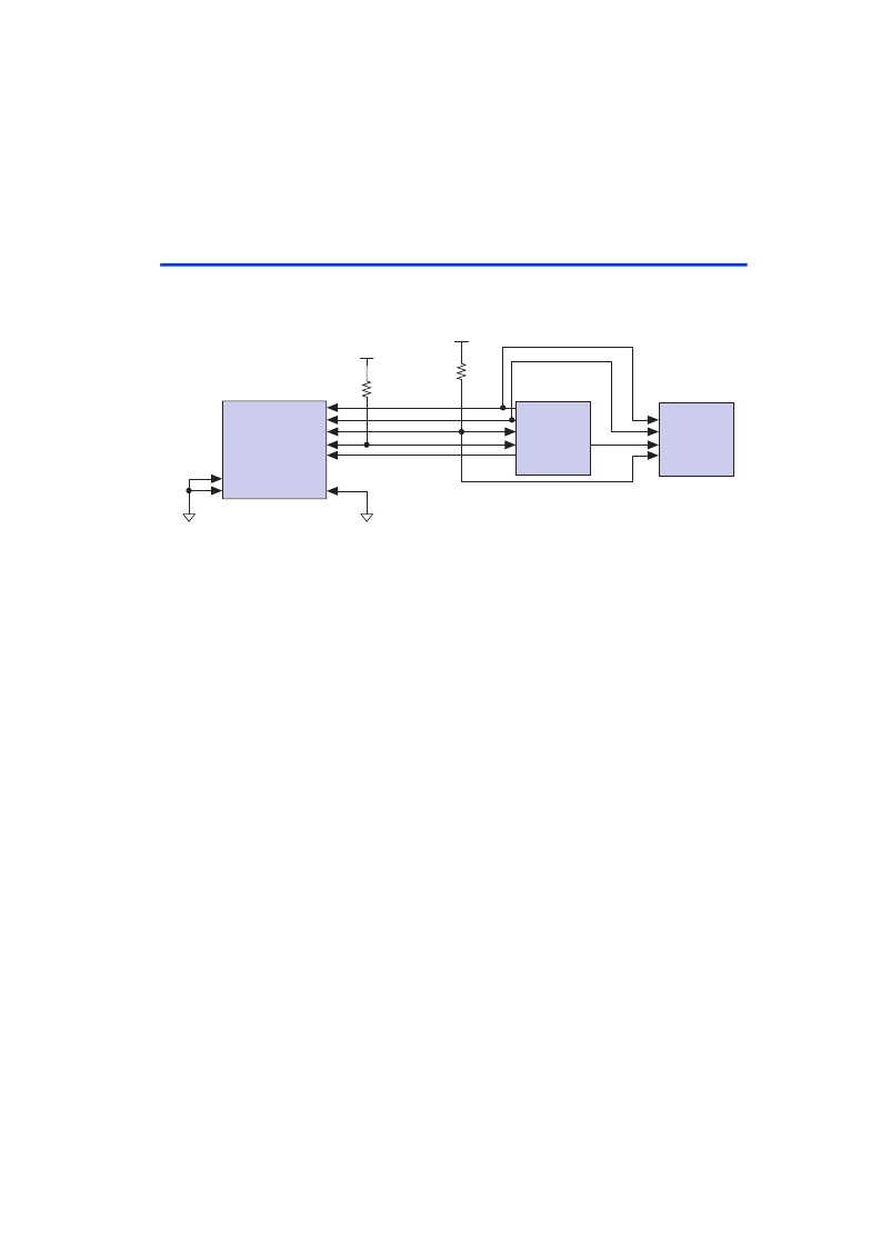
Figure 5. APEX II, APEX 20K, Mercury, ACEX 1K, FLEX 10K, or FLEX 6000 Device Configured with Two EPC2
or EPC1 Configuration Devices
Note (1)
Notes to
Figure 5
:
(1)
Do not use EPC2 devices to configure FLEX 6000 devices.
(2)
The pull-up resistor should be connected to the same supply voltage as the configuration device.
(3)
All pull-up resistors are 1 k
(APEX 20KE pull-resistors are 10 k
). The
OE
and
nCS
pins on EPC2 devices have
internal, user-configurable 1-k
pull-up resistors. If internal pull-up resistors are used, external pull-up resistors
should not be used on these pins.
(4)
The diagram shows an APEX II, APEX 20K, Mercury, ACEX 1K, and FLEX device, which has
MSEL0
and
MSEL1
tied to ground. For FLEX 6000 devices,
MSEL
is tied to ground, and the
DATA0
pin is named
DATA
. EPC8, EPC16,
and EPC2 devices cannot be used with FLEX 6000 devices. All other connections are the same for FLEX 6000
devices. The Quartus II software uses the internal pull-up resistors by default. To turn off the internal pull-up
resistors, check the
Disable nCS and OE pull-ups on configuration device
option when generating programming files.
(5)
EPC4, EPC8, and EPC16 devices cannot be cascaded.
(6)
The
nINIT_CONF
pin is only available on EPC2 devices and has an internal pull up of 1 k
that is always active. If
nINIT_CONF
is not available or not used,
nCONFIG
must be pulled to V
CC
either directly or through a 1-k
resistor.
V
CC
V
CC
GND
GND
(2, 3)
DCLK
DATA
nCS
OE
(2, 3)
LUT-Based PLD (4)
MSEL0
MSEL1
DCLK
DATA0
nSTATUS
CONF_DONE
nCONFIG
nCE
Configuration
Device 1
DCLK
DATA
OE
nCS
nINIT_CONF (6)
Configuration
Device 2
(5)
nCASC
相关PDF资料 |
PDF描述 |
|---|---|
| EPC8 | Configuration Devices for SRAM-Based LUT Devices |
| EPC1 | 433800612 |
| EPC1 | Configuration Devices for SRAM-Based LUT Devices |
| EPC1064 | Configuration Devices for SRAM-Based LUT Devices |
| EPC1064V | Configuration Devices for SRAM-Based LUT Devices |
相关代理商/技术参数 |
参数描述 |
|---|---|
| EPC-4 | 制造商:Curtis Industries 功能描述: |
| EPC40-30B25 | 制造商:Pulse 功能描述:- Bulk |
| EPC-440-0.9 | 制造商:EPIGAP 制造商全称:EPIGAP 功能描述:Photodiode-Chip |
| EPC-440-1.4 | 制造商:EPIGAP 制造商全称:EPIGAP 功能描述:Photodiode-Chip |
| EPC-440-2.5 | 制造商:EPIGAP 制造商全称:EPIGAP 功能描述:Photodiode-Chip |
发布紧急采购,3分钟左右您将得到回复。