- 您现在的位置:买卖IC网 > PDF目录17112 > EVAL-ADUC841QSZ (Analog Devices Inc)KIT DEV FOR ADUC841 QUICK START PDF资料下载
参数资料
| 型号: | EVAL-ADUC841QSZ |
| 厂商: | Analog Devices Inc |
| 文件页数: | 64/88页 |
| 文件大小: | 0K |
| 描述: | KIT DEV FOR ADUC841 QUICK START |
| 产品培训模块: | Process Control |
| 标准包装: | 1 |
| 系列: | QuickStart™ 套件 |
| 类型: | MCU |
| 适用于相关产品: | ADuC841 |
| 所含物品: | 评估板、电源、缆线、软件和说明文档 |
| 产品目录页面: | 739 (CN2011-ZH PDF) |
| 相关产品: | ADUC841BCPZ62-3-ND - IC MCU 62K FLASH ADC/DAC 56LFCSP ADUC841BCPZ62-5-ND - IC MCU 62K FLASH ADC/DAC 56LFCSP ADUC841BCPZ8-3-ND - IC MCU 8KB FLASH ADC/DAC 56LFCSP ADUC841BCPZ8-5-ND - IC MCU 8KB FLASH ADC/DAC 56LFCSP ADUC841BSZ62-5-ND - IC ADC/DAC 12BIT W/MCU 52-MQFP ADUC841BSZ62-3-ND - IC ADC/DAC 12BIT W/MCU 52-MQFP |
| 其它名称: | EVAL-ADUC841QS EVAL-ADUC841QS-ND |
第1页第2页第3页第4页第5页第6页第7页第8页第9页第10页第11页第12页第13页第14页第15页第16页第17页第18页第19页第20页第21页第22页第23页第24页第25页第26页第27页第28页第29页第30页第31页第32页第33页第34页第35页第36页第37页第38页第39页第40页第41页第42页第43页第44页第45页第46页第47页第48页第49页第50页第51页第52页第53页第54页第55页第56页第57页第58页第59页第60页第61页第62页第63页当前第64页第65页第66页第67页第68页第69页第70页第71页第72页第73页第74页第75页第76页第77页第78页第79页第80页第81页第82页第83页第84页第85页第86页第87页第88页
ADuC841/ADuC842/ADuC843
Rev. 0 | Page 67 of 88
Mode 3: 9-Bit UART with Variable Baud Rate
Mode 3 is selected by setting both SM0 and SM1. In this mode,
the 8051 UART serial port operates in 9-bit mode with a vari-
able baud rate determined by either Timer 1 or Timer 2. The
operation of the 9-bit UART is the same as for Mode 2, but the
baud rate can be varied as for Mode 1.
In all four modes, transmission is initiated by any instruction
that uses SBUF as a destination register. Reception is initiated in
Mode 0 by the condition RI = 0 and REN = 1. Reception is
initiated in the other modes by the incoming start bit if REN = 1.
UART Serial Port Baud Rate Generation
Mode 0 Baud Rate Generation
The baud rate in Mode 0 is fixed.
Mode 0 Baud Rate = (Core Clock Frequency/12)
Mode 2 Baud Rate Generation
The baud rate in Mode 2 depends on the value of the SMOD bit
in the PCON SFR. If SMOD = 0, the baud rate is 1/32 of the
core clock. If SMOD = 1, the baud rate is 1/16 of the core clock:
Mode 2 Baud Rate = (2SMOD/32 × [Core Clock Frequency])
Modes 1 and 3 Baud Rate Generation
The baud rates in Modes 1 and 3 are determined by the over-
flow rate in Timer 1 or Timer 2, or in both (one for transmit
and the other for receive).
Timer 1 Generated Baud Rates
When Timer 1 is used as the baud rate generator, the baud rates
in Modes 1 and 3 are determined by the Timer 1 overflow rate
and the value of SMOD as follows:
Modes 1 and 3 Baud Rate = (2SMOD/32 × (Timer 1 Overflow Rate)
The Timer 1 interrupt should be disabled in this application.
The timer itself can be configured for either timer or counter
operation, and in any of its three running modes. In the most
typical application, it is configured for timer operation in the
autoreload mode (high nibble of TMOD = 0010 binary). In that
case, the baud rate is given by the formula
Modes 1 and 3 Baud Rate =
(2SMOD/32) × (Core Clock/ [256 TH1])
Timer 2 Generated Baud Rates
Baud rates can also be generated using Timer 2. Using Timer 2
is similar to using Timer 1 in that the timer must overflow 16
times before a bit is transmitted/received. Because Timer 2 has a
16-bit autoreload mode, a wider range of baud rates is possible
using Timer 2.
Modes 1 and 2 Baud Rate = (1/16) × (Timer 2 Overflow Rate)
Therefore, when Timer 2 is used to generate baud rates, the
timer increments every two clock cycles rather than every core
machine cycle as before. Thus, it increments six times faster
than Timer 1, and therefore baud rates six times faster are possi-
ble. Because Timer 2 has 16-bit autoreload capability, very low
baud rates are still possible.
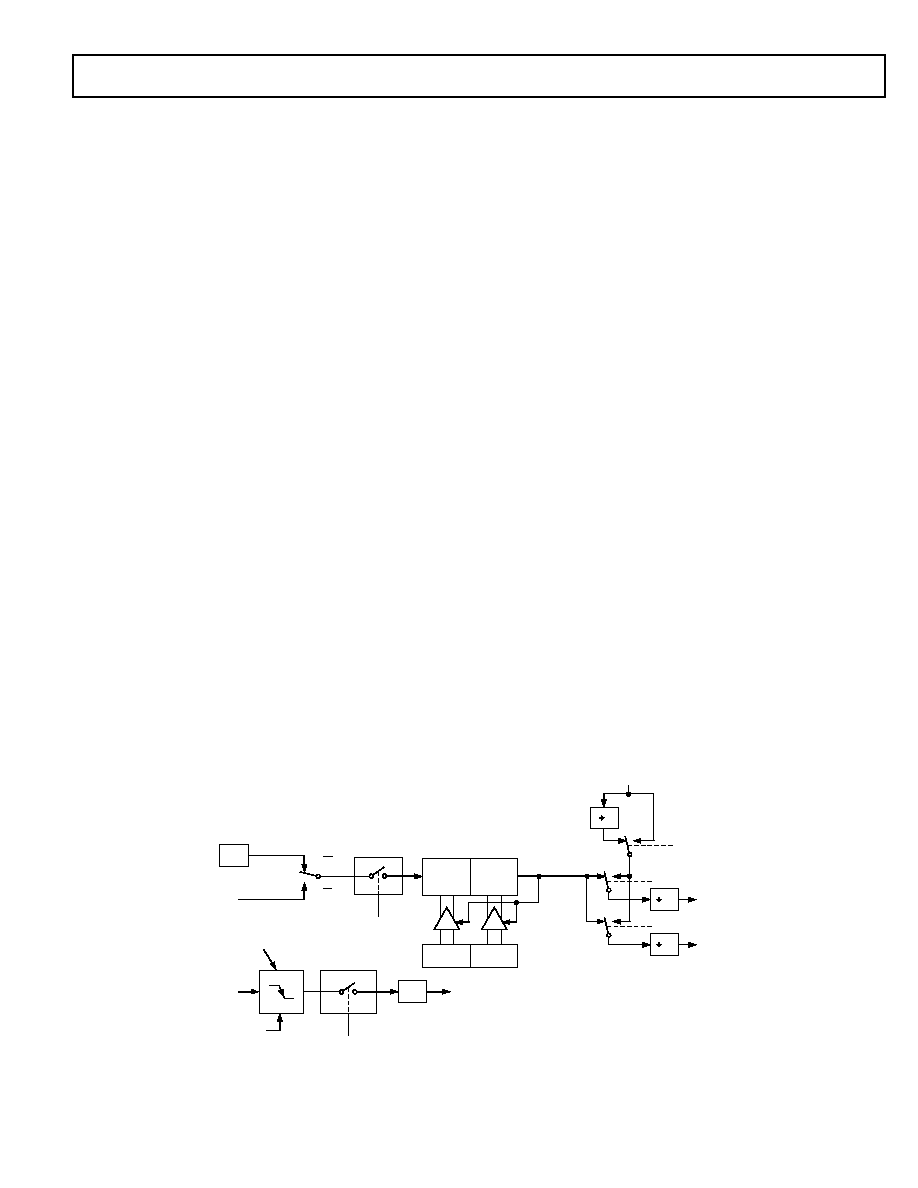
Timer 2 is selected as the baud rate generator by setting the
TCLK and/or RCLK in T2CON. The baud rates for transmit
and receive can be simultaneously different. Setting RCLK and/
or TCLK puts Timer 2 into its baud rate generator mode as
shown in Figure 73.
In this case, the baud rate is given by the formula
Modes 1 and 3 Baud Rate =
(Core Clock)/(16 × [65536 (RCAP 2H, RCAP 2L)])
CORE
CLK*
T2
PIN
TR2
CONTROL
TL2
(8 BITS)
TH2
(8 BITS)
RELOAD
EXEN2
CONTROL
T2EX
PIN
TRANSITION
DETECTOR
EXF 2
TIMER 2
INTERRUPT
NOTE: AVAILABILITY OF ADDITIONAL
EXTERNAL INTERRUPT
RCAP2L
RCAP2H
TIMER 2
OVERFLOW
2
16
RCLK
TCLK
RX
CLOCK
TX
CLOCK
0
1
0
SMOD
TIMER 1
OVERFLOW
C/ T2 = 0
C/ T2 = 1
*CORE CLK IS DEFINED BY THE CD BITS IN PLLCON
03260-
0-
073
Figure 73. Timer 2, UART Baud Rates
相关PDF资料 |
PDF描述 |
|---|---|
| HBM11DRAI | CONN EDGECARD 22POS R/A .156 SLD |
| EVAL-ADUC834QSZ | KIT DEV QUICK START ADUC834 |
| EVAL-ADUC847QSZ | KIT DEV QUICK START FOR ADUC847 |
| GBM24DTKT | CONN EDGECARD 48POS DIP .156 SLD |
| EVAL-ADUC7026QSZ | KIT DEV FOR ADUC7026/7027 |
相关代理商/技术参数 |
参数描述 |
|---|---|
| EVAL-ADUC842QS | 功能描述:KIT DEV FOR ADUC842 QUICK START RoHS:否 类别:编程器,开发系统 >> 通用嵌入式开发板和套件(MCU、DSP、FPGA、CPLD等) 系列:QuickStart™ 套件 产品培训模块:Blackfin® Processor Core Architecture Overview Blackfin® Device Drivers Blackfin® Optimizations for Performance and Power Consumption Blackfin® System Services 特色产品:Blackfin? BF50x Series Processors 标准包装:1 系列:Blackfin® 类型:DSP 适用于相关产品:ADSP-BF548 所含物品:板,软件,4x4 键盘,光学拨轮,QVGA 触摸屏 LCD 和 40G 硬盘 配用:ADZS-BFBLUET-EZEXT-ND - EZ-EXTENDER DAUGHTERBOARDADZS-BFLLCD-EZEXT-ND - BOARD EXT LANDSCAP LCD INTERFACE 相关产品:ADSP-BF542BBCZ-4A-ND - IC DSP 16BIT 400MHZ 400CSBGAADSP-BF544MBBCZ-5M-ND - IC DSP 16BIT 533MHZ MDDR 400CBGAADSP-BF542MBBCZ-5M-ND - IC DSP 16BIT 533MHZ MDDR 400CBGAADSP-BF542KBCZ-6A-ND - IC DSP 16BIT 600MHZ 400CSBGAADSP-BF547MBBCZ-5M-ND - IC DSP 16BIT 533MHZ MDDR 400CBGAADSP-BF548BBCZ-5A-ND - IC DSP 16BIT 533MHZ 400CSBGAADSP-BF547BBCZ-5A-ND - IC DSP 16BIT 533MHZ 400CSBGAADSP-BF544BBCZ-5A-ND - IC DSP 16BIT 533MHZ 400CSBGAADSP-BF542BBCZ-5A-ND - IC DSP 16BIT 533MHZ 400CSBGA |
| EVAL-ADUC842QS1 | 制造商:AD 制造商全称:Analog Devices 功能描述:MicroConverter 12-Bit ADCs and DACs with Embedded High Speed 62-kB Flash MCU |
| EVAL-ADUC842QSP1 | 制造商:AD 制造商全称:Analog Devices 功能描述:MicroConverter 12-Bit ADCs and DACs with Embedded High Speed 62-kB Flash MCU |
| EVAL-ADUC842QSP2 | 制造商:AD 制造商全称:Analog Devices 功能描述:MicroConverter 12-Bit ADCs and DACs with Embedded High Speed 62-kB Flash MCU |
| EVAL-ADUC842QSPZ | 功能描述:KIT DEV QUICK START ADUC842 RoHS:是 类别:编程器,开发系统 >> 通用嵌入式开发板和套件(MCU、DSP、FPGA、CPLD等) 系列:QuickStart™ PLUS 套件 标准包装:1 系列:PICDEM™ 类型:MCU 适用于相关产品:PIC10F206,PIC16F690,PIC16F819 所含物品:板,线缆,元件,CD,PICkit 编程器 产品目录页面:659 (CN2011-ZH PDF) |
发布紧急采购,3分钟左右您将得到回复。